WELD-02 · Foundation · approximately 30 minutes with practice
Read the location before you read the weld.
A correctly recognised weld symbol can still lead to the wrong work if it is assigned to the wrong joint or side. This lesson follows the original teaching board: locate the joint, identify the system and interpret the designated side.
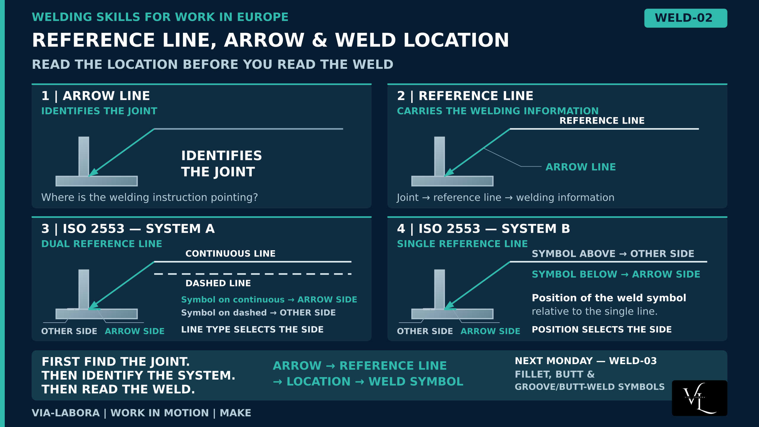
View the original board at full size (new tab)
Situation from work
A bracket will become difficult to access after installation. You recognise the weld type, but you are uncertain which side is specified.
Do not move the weld to the accessible side. Establish the location and clarify the assembly sequence before carrying out the affected operation.
Location reading protects more than the weld itself: it supports preparation, access and team coordination.
Who is this for, and what will you gain?
For welders, fitters, fabricators, candidates and team leaders working with drawings.
You will gain a method for connecting notation to a physical joint and clearer language for explaining location questions.
Review WELD-01 first if the complete designation and system identification are unfamiliar.
Learning objectives
After this lesson, you should be able to:
- Distinguish arrow line and reference line.
- Explain arrow side and other side in the simple examples.
- Apply the basic system A/B side rules.
- Reject unreliable physical left/right or top/bottom shortcuts.
- Identify an unresolved location.
- Communicate a specific clarification request.
Technical explanation
Arrow line
Follow the arrowhead to the indicated joint and compare the relevant views or sections.
The slope or approach direction of the arrow is not a universal rule for physical weld position.
An arrow arriving from the right does not automatically mean “right-side weld”.
Reference line
The reference line organises symbolic information. It is distinct from the leader running towards the joint.
Some requirements may appear in notes or referenced documents rather than directly beside the elementary symbol.
Arrow side and other side
These are relative descriptions of the joint indicated by the arrow.
In the simple T-joint examples, one internal corner illustrates the arrow side and the opposite corner the other side. Do not extend that picture mechanically to every geometry.
System A
For the side-designating elementary symbols discussed here:
- Continuous reference line → arrow side.
- Dashed reference line → other side.
Read the identity of the line carrying the symbol.
The dashed line can be placed above or below the continuous line. Its identity, rather than an above/below shortcut, is what matters.
System B
For the examples discussed here:
- Below the single reference line → arrow side.
- Above the single reference line → other side.
“Below” describes notation on the page. It does not mean the underside of a plate.
Both sides and specialised details
Where both sides are specified, read their requirements separately. Do not assume identical dimensions or weld types.
Some asymmetric preparations require attention to which member is identified for preparation. A change of direction in an arrow line must not automatically be dismissed as decoration.
These introductory rules are not a complete guide to specialised symbols, multiple reference lines or preparation details.
Confirm the applicable standard from the documentation. One visible line in a cropped image is insufficient to establish AWS.
Terminology
| EN | PL | Working meaning |
|---|---|---|
| Arrow line | Linia strzałkowa | Leader to the indicated joint. |
| Arrowhead | Grot strzałki | End identifying the relevant location. |
| Reference line | Linia odniesienia | Organises symbolic information. |
| Continuous line | Linia ciągła | Unbroken system A reference line. |
| Dashed line | Linia przerywana | Second system A reference line. |
| Arrow side | Strona strzałki | Side identified in the joint context. |
| Other side | Strona przeciwna | Opposite side of that joint. |
| Section view | Przekrój | View revealing the represented internal relationship. |
Practical interpretation: step by step
- Confirm the drawing and revision.
- Establish the applicable system.
- Locate the arrowhead and joint.
- Compare views to understand the relative sides.
- Apply line identity in A or symbol position in B.
- State the designated side in words.
- Continue reading the remaining requirements.
- Clarify uncertainty before the affected operation.
This is a teaching workflow, not a prescribed ISO sequence.
- System A: continuous line → arrow side
- System A: dashed line → other side
- System B: below line → arrow side
- System B: above line → other side
Worked example
Training detail VL-L201 declares system A.
The elementary symbol is associated with the dashed reference line, which appears above the continuous line.
Reasoning:
- The system is known.
- The relevant line is dashed.
- The specified side is therefore the other side.
- Its position above the continuous line does not reverse that conclusion.
Contrast:
In a declared system B example, a symbol below the single line indicates the arrow side.
These descriptions are training examples, not complete production designations.
Further workshop situations
A poor scan makes the dashed line indistinguishable from printing damage.
Obtain a readable complete drawing. Do not turn image damage into a technical interpretation.
A specified weld becomes inaccessible after fitting.
Confirm the location and sequence with the responsible person. Access does not authorise relocating the weld.
Common mistakes
- Reading the weld type before locating the joint.
- Using arrow direction as a left/right rule.
- Applying system B above/below rules to system A.
- Treating below-line placement as physical underside.
- Assuming both sides are identical.
- Interpreting a cropped or unreadable image confidently.
- Ignoring an unfamiliar asymmetric preparation.
Practical exercise
Identify the side or explain what is missing:
A. System A; elementary symbol associated with the continuous line.
B. System A; symbol on the dashed line, drawn above the continuous line.
C. System B; symbol below the single reference line.
D. Cropped image; one line and symbol above it; no system confirmed.
- A. System A, symbol on continuous line.
- B. System A, symbol on dashed line above continuous line.
- C. System B, symbol below single line.
- D. Cropped image; system unknown.
Show suggested answers
A: Arrow side.
B: Other side; line identity controls.
C: Arrow side; below-line placement controls.
D: Insufficient context to establish the system reliably.
Success criterion: explain the governing rule, not only the answer.
Knowledge check
1. Does a dashed line above the continuous line in system A indicate arrow side?
Show answer
No. A symbol associated with the dashed line indicates the other side.
2. Does below-line placement in system B mean underneath the component?
Show answer
No. It indicates arrow side.
3. Does an arrow arriving from the right create a right-side rule?
Show answer
No. Read the joint and relative sides.
4. Can different systems indicate the same physical side?
Show answer
Yes.
5. Can an inaccessible weld be moved by preference?
Show answer
No. Clarify location and sequence.
6. Do side indications alone establish identical welds on both sides?
Show answer
No. Read each side’s requirements.
Use it in a technical interview
Describe an actual example of following the arrow, comparing views and establishing the side.
Useful wording:
“I establish the system first. Then I identify the joint and apply the relevant side rule. If the views are unclear, I raise the specific detail before preparation.”
Do not claim independent competence beyond your experience.
Use it with your team
On an approved training drawing, ask:
- Which joint does the arrow identify?
- Which system is declared?
- Which side is specified?
- Will the assembly sequence preserve access?
Have a second person explain the same interpretation independently. Resolve disagreements through the workplace process.
Key takeaways
Find the joint.
Identify the system.
System A: read line identity.
System B: read above/below placement.
Do not confuse notation with physical orientation.
Clarify unresolved details.
Practical bonus — Location Check Card
Drawing/revision: ______
Detail: ______
System: ______
Indicated joint: ______
Designated side and reason: ______
Access or sequence question: ______
☐ Views checked.
☐ Appropriate side rule applied.
☐ Remaining requirements reviewed.
☐ Unresolved questions raised.
Ordinary examples:
A: continuous → arrow side; dashed → other side.
B: below → arrow side; above → other side.
Check specialised cases against the applicable documentation.
WELD-02 · 2026-11-06 · https://via-labora.com/academy/welding/weld-02-reference-line-arrow-weld-location/
Previous / next
Previous: WELD-01 — How to Read Welding Symbols in Europe.
Next: WELD-03 — Fillet, Butt & Joint/Weld Terminology.
Candidates
Describe drawing-location experience alongside processes, materials, positions and fabrication tasks.
Ask VIA-LABORA about welding opportunities and the Technical Talent Pool:
technicals@via-labora.com
WhatsApp +48 504 016 136
Employers
Discuss preselection according to processes, materials, positions, thickness/diameter range, drawing competence, WPS experience, certificates and fabrication work.
marcin.ciupka@via-labora.com
References and scope
ISO 2553:
Open reference
ISO terminology:
Open reference
Editorial check: 6 November 2026.
Use the applicable project edition. Examples are schematic and do not replace production instructions.
Additional explanations and original examples
Core theory
1. The arrow line connects the instruction to the joint
Follow the arrowhead to the indicated joint. Compare the relevant views or sections if several components meet nearby.
The slope of the arrow line does not, by itself, tell you which side must be welded.
An arrow approaching from the upper right does not mean “weld the top”, and an arrow approaching from the left does not create a universal “left-side weld” rule.
2. The reference line organises the symbolic information
The reference line is the part of the designation used to arrange the weld symbols and associated information.
Do not confuse it with the arrow line that leads towards the joint.
Some supporting requirements are elsewhere in the drawing or referenced documents. “Carries the welding information” is a useful introductory description, not a statement that every requirement must appear directly on the line.
3. Arrow side and other side are relative terms
For the simple joint examples in this lesson:
- Arrow side identifies the side indicated by the arrow.
- Other side identifies the opposite side.
These terms do not mean permanently left/right, near/far or top/bottom.
In a sectional T-joint example, the arrow can identify one internal corner. The opposite corner illustrates the other side. This is a teaching example, not a universal picture for every joint geometry.
Use the arrow together with the drawing views to establish the intended relationship.
ISO terminology reference:
Open reference
4. System A: read the line identity
System A uses a continuous and a dashed reference line.
For the side-designating elementary symbols discussed here:
- Symbol associated with the continuous line: arrow side.
- Symbol associated with the dashed line: other side.
Do not replace this with “above means one side and below means the other”.
The dashed line can be arranged above or below the continuous line. Read which line the symbol belongs to.
5. System B: read the symbol position
System B uses a single reference line.
For the side-designating elementary symbols discussed here:
- Symbol below the reference line: arrow side.
- Symbol above the reference line: other side.
Below the reference line does not mean the underside of the component. It identifies the arrow side according to the drawing convention.
6. Information on both sides
If a designation specifies welds on both sides, interpret the requirements assigned to each side.
Do not assume the weld types or dimensions must be identical.
This lesson establishes how the sides are identified. Read the remaining requirements through the complete designation and supporting documentation.
7. Recognise the limits of the simplified examples
These rules introduce ordinary side designation. They are not a complete guide to every symbol, multi-reference-line arrangement or specialised joint.
Some asymmetric preparations require the arrow to identify the member to be prepared. A change of direction in an arrow line must not automatically be treated as decoration.
Do not use the simple T-joint examples to decide which member needs preparation in an unfamiliar asymmetric detail. Check the specified preparation and applicable rules.
Keep the full reference context available; a single line in a cropped image is not enough to establish the governing standard.
Primary standard reference:
Open reference
Original practical examples
Example 1 — System A, dashed-line designation
Training drawing VL-L201 declares ISO 2553 system A.
The arrow identifies one side of a simple bracket connection. The elementary symbol is associated with the dashed reference line.
Interpretation: the indicated weld is on the other side.
Do not select the physical side solely because the symbol appears above or below the continuous line.
Example 2 — System B, symbol below
Training drawing VL-L202 declares ISO 2553 system B.
The elementary symbol is below the single reference line.
Interpretation: the indicated weld is on the arrow side.
This does not mean “weld underneath the base plate”. Locate the side through the arrow and drawing views.
Example 3 — Same location, different notation
Two training drawings show the same simple joint and arrow-side weld.
One uses system A with the elementary symbol associated with the continuous line. The other uses system B with the symbol below the single line.
The notation differs, but the intended side is the same.
This is the connection between the WELD-01 anchor and the detailed reading method in this lesson.
Example 4 — Unclear scan
A scan is too poor to distinguish a dashed line from broken printing. The drawing notes are cropped out.
Interpretation: the image is insufficient to establish a reliable answer.
Obtain a readable complete drawing and confirm the applicable system. Do not interpret image damage as technical notation.