SAME POINT. DIFFERENT COORDINATES.
A position value only makes sense when you know its reference.
The same physical position can have different coordinate values when described relative to different origins.
Understanding that difference helps you interpret the machine display, discuss a setup, and recognise when information needs clarification.
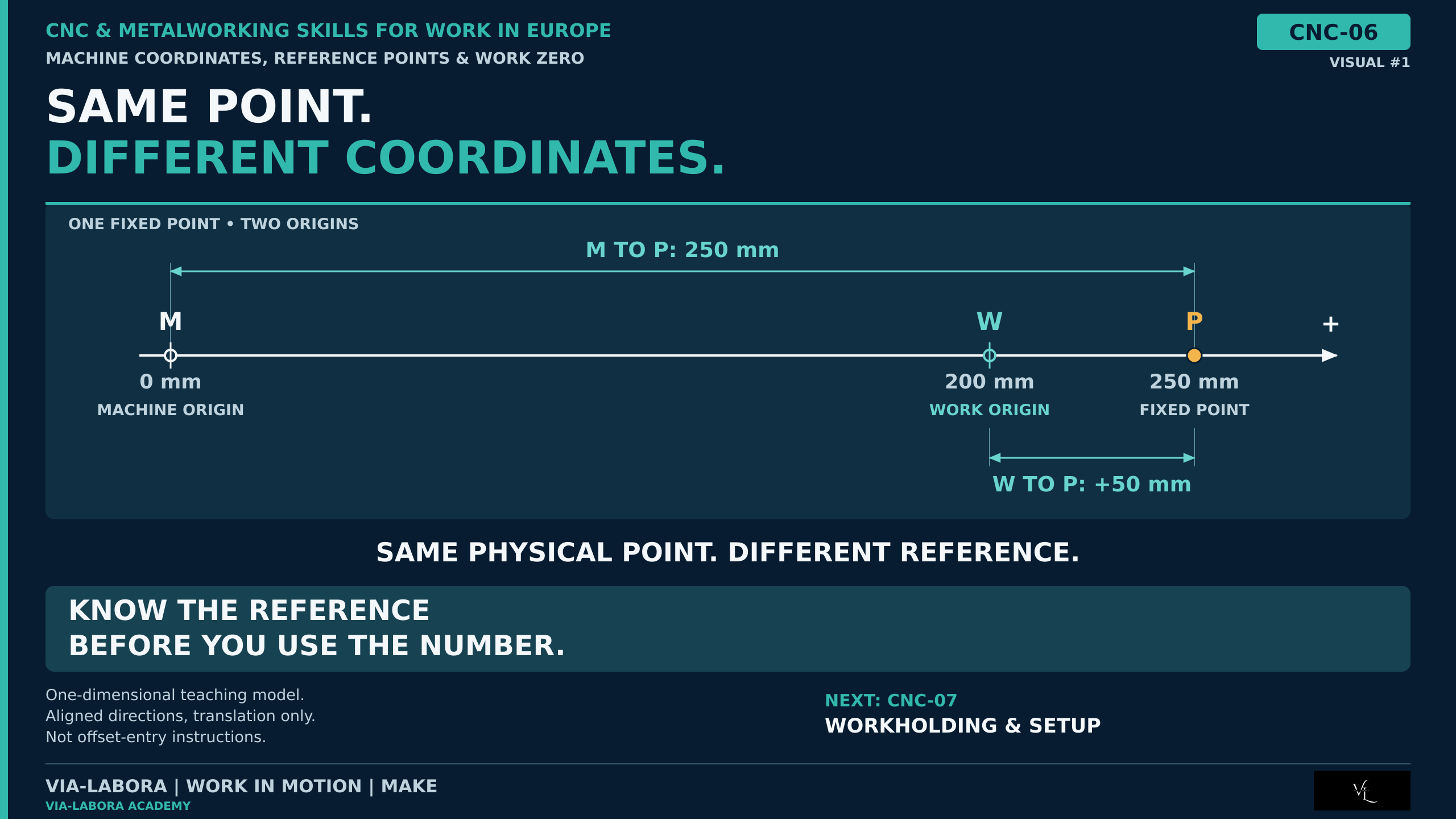
*Conceptual illustration, not a machine operating procedure. Actual displays and coordinate relationships depend on the machine, control configuration, active transformations, and tool compensation.*
Situation from Work
An operator changes the position display. The number changes, but the machine has not moved.
A colleague assumes that the workpiece position has been lost.
Before taking action, they need to establish which coordinate display is active and what physical position it represents.
Changing the description of a position is different from physically moving an axis.
Changing stored coordinate data can also change how future movements are interpreted. It must not be treated as a harmless display adjustment.
Who Is This For?
This lesson is for beginners, operators, setters, programmers, production managers, HR professionals, and technical recruiters who need to understand coordinate terminology.
Recommended previous lesson: CNC-05 — CNC Controls: Different Systems, Same Goal.
You need basic signed-number arithmetic. You do not need to enter data or operate a machine.
What Will You Gain?
You will learn to separate:
- Machine coordinates.
- Axis referencing and reference positions.
- Work coordinates and work zero.
- Drawing references and formal datums.
You will also learn why a displayed zero does not automatically mean a safe location.
Learning Objectives
After this lesson, you should be able to:
- Explain why the same point can have different coordinate values.
- Distinguish machine coordinates from work coordinates.
- Explain why axis referencing does not locate the workpiece.
- Separate a drawing datum from CNC work zero.
- Solve a simple translation-only coordinate example.
- Identify information needed before interpreting a real position display.
- Recognise which questions require machine-specific clarification.
Technical Foundation
1. A coordinate needs a reference
A coordinate is a numerical description relative to a coordinate system.
Its meaning depends on the origin, axis directions, units, and applicable transformations.
The number “50” is incomplete without that context.
Also establish what the display represents. Depending on the system and selected view, it may describe axis positions or a calculated position associated with the tool or another reference.
Do not assume that every displayed value refers to the tool tip.
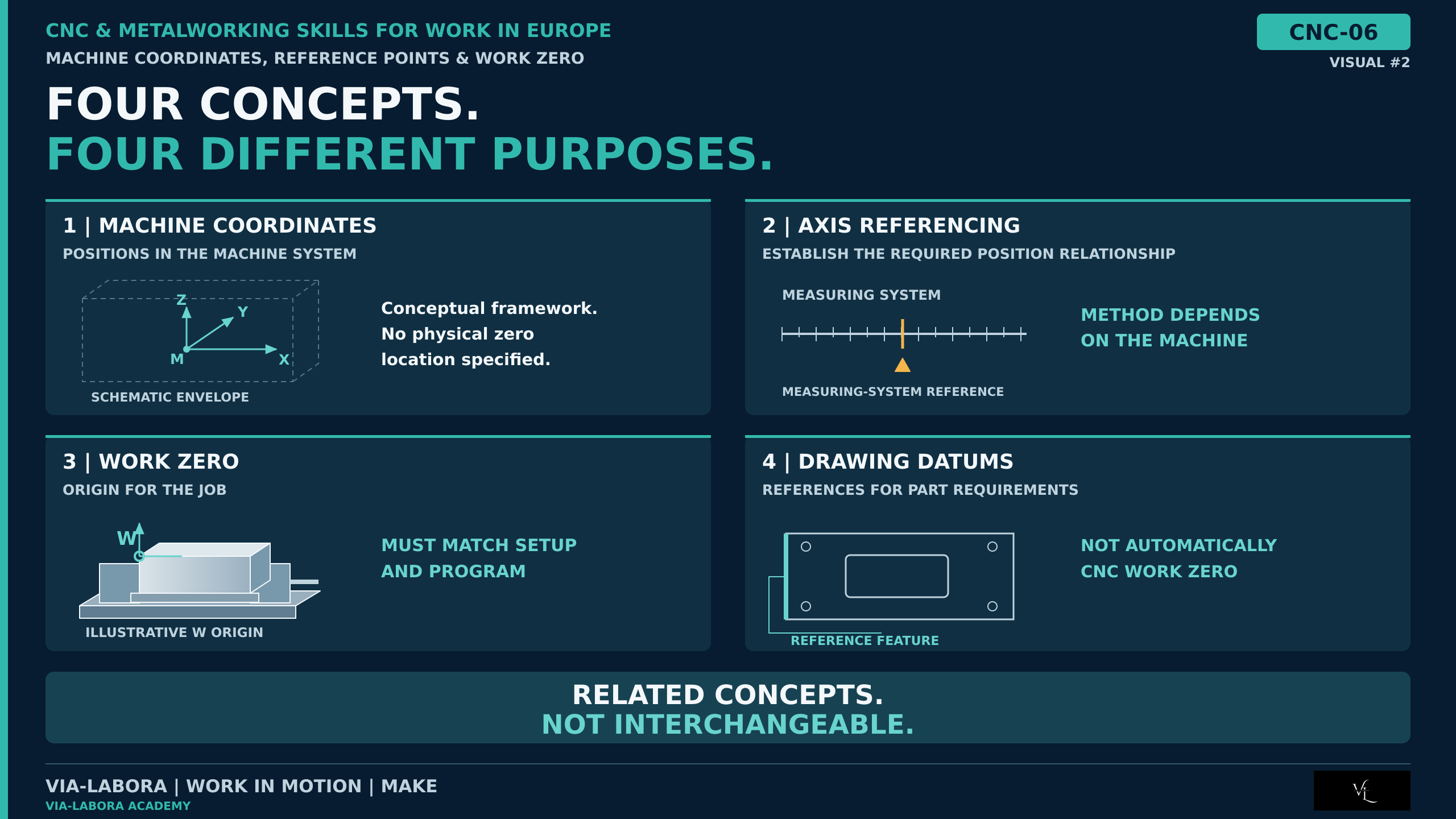
2. Machine coordinates
The machine coordinate system provides a defined reference for describing machine positions.
Its origin and orientation are established by the machine design and configuration.
Machine zero is not automatically the workpiece corner, table surface, or a convenient inspection reference.
Do not assume that a machine-coordinate zero is safe to approach.
3. Axis referencing
Where required, a referencing procedure establishes the necessary relationship between axis position and the position-measuring system.
The procedure depends on the machine and feedback technology.
Some systems require reference movement under specified conditions. Others use absolute position information and have different requirements.
Do not teach one universal power-up or reference-return sequence.
A reference position used during referencing need not be identical to the machine-coordinate origin.
Referencing does not identify where the workpiece has been clamped.
4. Work coordinates and work zero
A work coordinate system describes positions for a job.
Work zero is its origin.
Its location must agree with the approved setup and program assumptions. It can be associated with a chosen feature or constructed location; it does not have to be a physical corner.
There may be several work coordinate systems in a job.
Their selection, data structure, and implementation are machine- and control-specific.
5. Work offsets
In a simple setup with aligned axes, work-offset data relates the work origin to the machine coordinate system.
More complex work can involve rotations, additional shifts, tilted planes, kinematic transformations, and tool compensation.
Therefore, a simple subtraction diagram explains one relationship. It is not a universal reconstruction of every machine display or an instruction for entering values.
6. Drawing references and formal datums
Drawing references and datums help define part requirements.
CNC work zero supports the manufacturing coordinate framework.
Process planning may connect them, but they are not automatically identical.
A drawing can specify a requirement relative to a datum while the manufacturing program uses a different, deliberately chosen origin.
The setup and inspection process must preserve the required relationships.
7. Display change, data change, physical movement
Keep these separate:
- Selecting another display can change the numbers shown without movement.
- Editing an origin or transformation can change the coordinate interpretation without immediate movement.
- Executing a movement changes physical position.
- A later movement can be affected by previously changed data.
Never infer safety from the absence of immediate movement.
Terminology EN / PL
| English | Polski |
|---|---|
| Coordinate system | Układ współrzędnych |
| Origin | Początek układu |
| Machine coordinates | Współrzędne maszynowe |
| Machine zero | Zero maszyny |
| Axis referencing | Referencja osi / ustalenie pozycji referencyjnej |
| Reference position | Pozycja referencyjna |
| Work coordinate system | Układ współrzędnych przedmiotu |
| Work zero | Zero przedmiotu / początek układu roboczego |
| Work offset | Przesunięcie układu roboczego |
| Transformation | Transformacja |
| Tool compensation | Korekcja / kompensacja narzędzia |
| Drawing datum | Baza rysunkowa / geometryczna |
| Position display | Wskazanie pozycji |
| Distance to go | Pozostała droga do zadanej pozycji |
Terms such as “home”, “datum”, and “reference” can be used differently in manuals and workplaces. Confirm the intended meaning.
Process Explanation
Before interpreting a position, ask:
- Which display and coordinate frame are active?
- What units and sign conventions apply?
- What physical point or axis position is represented?
- Which origin, shifts, and transformations are active?
- What tool compensation is relevant?
- Which approved instruction applies?
- Am I authorised to make the proposed change?
If the answer is uncertain, obtain clarification before movement or data editing.
Worked Example
One point, two coordinate descriptions
Assumptions:
- One dimension.
- Millimetres.
- Parallel positive directions.
- Translation only.
- No rotation, scaling, tool compensation, or kinematic transformation.
Machine origin M is 0.
Work origin W is located at machine coordinate 200 mm.
Point P is located at machine coordinate 250 mm.
The work coordinate of P is:
P_work = P_machine − W_machine
250 − 200 = +50 mm
Check the result
Starting at W = 200 and moving +50 along the illustrated direction reaches P = 250.
Change the reference
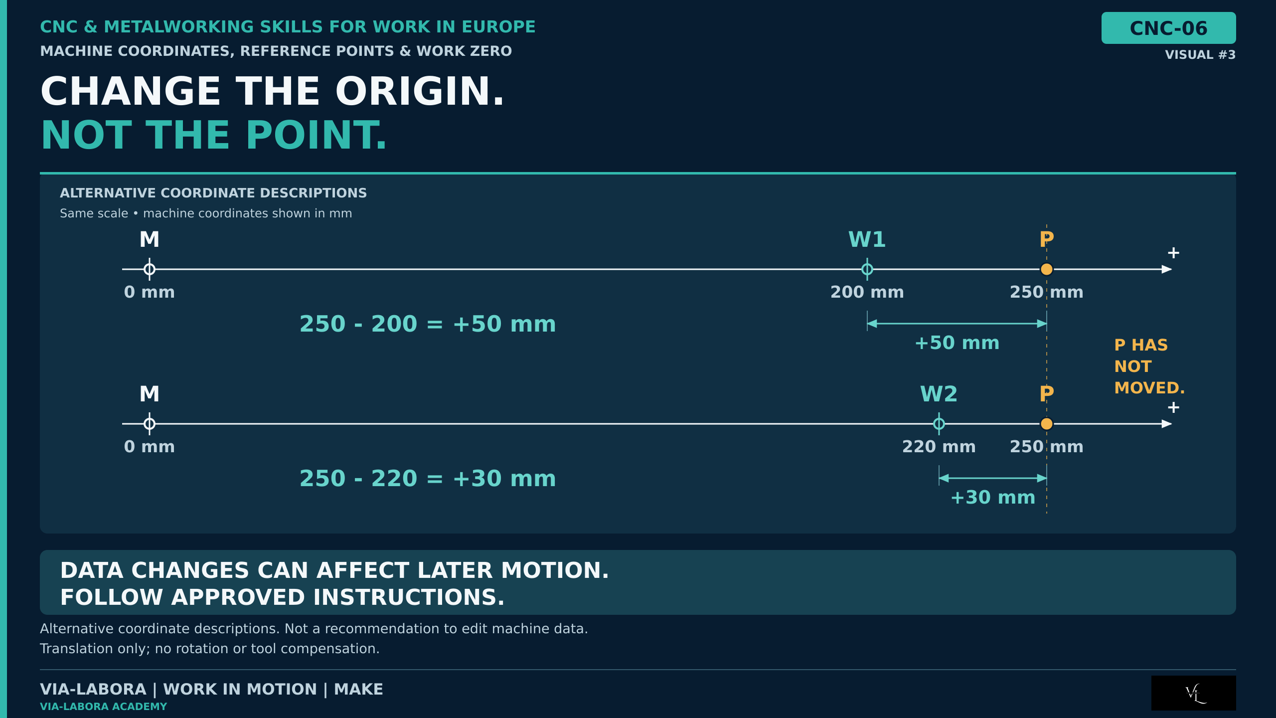
Keep P physically fixed at 250. Place the alternative work origin at 220.
250 − 220 = +30 mm
The point did not move. Its coordinate description changed.
Important boundary
These values are not instructions for entering a particular control’s offset table.
Control / Process Differences
FANUC, SINUMERIK, HEIDENHAIN, and MAZATROL may use different terminology, displays, data structures, and functions.
Confirm the actual manual and machine configuration.
Process differences also matter:
- TURN: axis conventions and diameter/radius representation require confirmation.
- MILL: work orientation, tool compensation, and possible transformations matter.
- BEND: programmed bend and backgauge data must not be interpreted as a milling coordinate system.
- CUT: sheet orientation, job origin, and the cutting system’s coordinate conventions require confirmation.
The common lesson is to identify the reference. The procedures are not interchangeable.
Common Mistakes
| Mistake | Better understanding |
|---|---|
| “The number changed, so the axis moved.” | Establish whether the display, data, or physical position changed. |
| “Referencing finds the workpiece.” | Referencing and locating the workpiece are separate tasks. |
| “Home and machine zero are always identical.” | Confirm the machine’s definitions. |
| “The drawing datum must be program zero.” | The process plan establishes the relationship. |
| “Zero is safe.” | Safety depends on the actual machine, tooling, and setup. |
| “Negative coordinates indicate a fault.” | The sign describes position relative to an origin. |
| “This subtraction works for every configuration.” | The example assumes aligned axes and translation only. |
| “No movement means the change was harmless.” | Changed data can affect later movements. |
Safety and Authorisation
Do not test coordinate assumptions by issuing a movement.
Do not change work origins, transformations, or tool data to make an unfamiliar display look familiar.
Follow approved referencing, setup, verification, and recovery instructions.
Operators interpret assigned information and report uncertainty. Setters establish setups within their authority. Programmers define program assumptions. Technologists coordinate process requirements. Service technicians address authorised machine and measuring-system issues.
Responsibilities and release authority are workplace-specific.
Practical Exercise
Use the simplified model:
P_work = P_machine − W_machine
| Case | P_machine | W_machine | Your answer |
|---|---|---|---|
| A | 310 mm | 240 mm | |
| B | −120 mm | −180 mm | |
| C | 30 mm | 70 mm |
Answers with reasoning
A: 310 − 240 = +70 mm.
B: −120 − (−180) = +60 mm. Subtracting the negative origin adds 180.
C: 30 − 70 = −40 mm. The point lies on the negative side of the work origin.
Scenario
A display changes from 250 to 50 without axis movement.
Can you conclude that work coordinates were selected?
Answer: it is one possible explanation, not a proven conclusion. Identify the display and active settings.
Knowledge Check
1. Does axis referencing locate the workpiece?
Show answer
No.
2. Is a reference position necessarily machine zero?
Show answer
No.
3. Is a drawing datum automatically work zero?
Show answer
No.
4. Can one physical point have different coordinates?
Show answer
Yes, relative to different coordinate systems.
5. Does displayed zero establish clearance?
Show answer
No.
6. Does the simple subtraction cover rotated or transformed systems?
Show answer
Not without additional treatment.
7. What should you do when the coordinate frame is uncertain?
Show answer
Clarify it through the applicable instructions and responsible person.
Use It in a Technical Interview
“I distinguish machine and work coordinates and confirm which display is active. I understand that referencing does not locate the workpiece. My authority to establish or change work zero depends on the assigned role.”
Describe actual experience. Explaining the concept is not proof of practical setup competence.
Use It With Your Team
Ask which origin, display, units, represented point, and transformations apply.
When reporting a problem, record the context rather than sending an isolated coordinate value.
Key Takeaways
- A position value requires a reference.
- Machine coordinates and work coordinates serve different purposes.
- Referencing and workpiece location are separate.
- Drawing datums and work zero are not automatically identical.
- Changing a coordinate description is different from movement.
- Coordinate-data changes can affect later movements.
- Know the reference before using the number.
Downloadable Resource
Coordinates: Know the Reference — Worksheet + Explained Answers
Includes the simplified example, signed-number exercises, answer explanations, interpretation checklist, and clarification record.
Use the supplied EN or PL PDF. It is a paper learning exercise, not a machine setup sheet.
Candidate CTA
Describe your actual experience with position displays, referencing, and work-coordinate tasks, including the supervision required.
Contact VIA-LABORA about your technical background.
B2B CTA
Define whether the role requires interpreting coordinates, establishing work zero, or approving setup changes.
Contact VIA-LABORA to discuss competence-based matching and onboarding.
Previous / Next Episode
← CNC-05 — CNC Controls: Different Systems, Same Goal
Next: CNC-07 — Workholding & Setup.
The next lesson connects the coordinate discussion with physically locating, supporting, and securing the workpiece.