How big? How long? How often?
Recognising the weld type and designated side is only part of reading the instruction. You also need to identify its cross-sectional size, required length and, for intermittent welds, the arrangement of the separate elements.
This lesson follows the three panels of the original WELD-04 board. It also explains a critical distinction: centre-to-centre pitch is not the same measurement as the clear gap between weld elements.
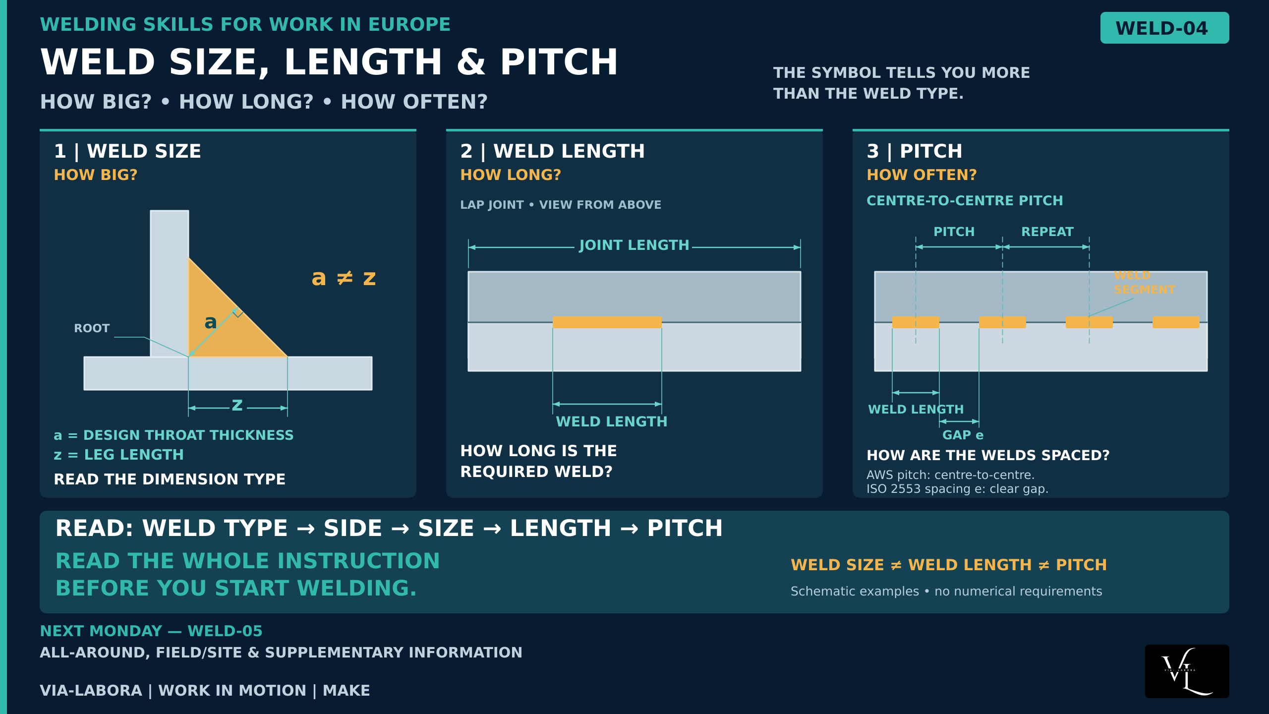
View original infographic full size (opens a new tab) ↗
- Distinguish nominal throat thickness from leg length.
- Read weld-element count, length and clear gap.
- Calculate repeat distance and occupied span under stated assumptions.
WELD-04 · Foundation · Estimated study time: 30–40 minutes, including practice
Why this matters at work
A fillet weld with the wrong size is not corrected simply by making it longer.
Likewise, three correctly sized weld elements can still form the wrong arrangement if their lengths or spacing are misread.
Before marking out a joint, distinguish:
- Cross-sectional dimensions.
- Longitudinal dimensions.
- The number and arrangement of weld elements.
This helps you prepare, execute and discuss the specified weld rather than an approximation based on appearance.
Learning objectives
After this lesson, you should be able to:
- Distinguish nominal throat thickness a from leg length z.
- Explain the limits of the ideal equal-leg conversion.
- Distinguish required weld length from overall joint length.
- Interpret the introductory ISO intermittent-weld dimension group n × l (e).
- Calculate centre-to-centre repeat distance from equal segment length and clear gap.
- Identify missing positioning information or an ambiguous spacing instruction.
Before you start
WELD-01 introduced the complete instruction.
WELD-02 established location.
WELD-03 distinguished joint configuration from weld type.
Use those skills here. First confirm the joint, system and weld type; then read dimensions.
This lesson concentrates on basic fillet-weld sizing and simple intermittent arrangements. It is not a weld-design calculation guide.
Core theory
1. Size: read the dimension type
The anchor shows two different dimensions:
- a: nominal throat thickness.
- z: leg length.
In the ideal equal-leg, flat-face fillet shown, a runs from the root to the face at right angles to that face. z runs along a fusion face from the root intersection to the toe.
The infographic’s “design throat thickness” wording describes the nominal design dimension. It does not establish measured penetration or internal quality.
ISO defines these quantities separately:
Open reference
A designation of a5 and one of z5 therefore communicate different dimension types, even though both contain the number 5.
Check drawing units rather than assuming them.
2. The equal-leg geometric relationship
For an ideal 90-degree fillet with equal legs and a flat face:
a = z / √2
a ≈ 0.707z
Therefore:
z ≈ 1.414a
This is geometry for that model, not a universal conversion for all weld profiles.
For example, if z = 6 mm:
a ≈ 4.24 mm.
Do not use this calculation to change a specified a6 weld into z6.
Unequal legs, different joint angles, curved faces and penetration-related requirements need their own interpretation. Do not credit extra reinforcement or penetration using this simple equation.
Supporting explanation:
Open reference
Ideal equal-leg, flat-face fillet in a 90° joint; no additional penetration or reinforcement. Not a production gauge or tolerance chart.
For this geometric model only: a = z / √2. Read the specified dimension; do not infer a production tolerance from this diagram.
3. Where dimensions appear
In ordinary ISO symbolic dimensioning, cross-sectional dimensions are placed to the left of the elementary symbol, and longitudinal information to the right.
Read any letter attached to the size value. It identifies what is being dimensioned.
This introductory pattern does not replace checking the complete designation, notes and applicable edition.
Do not interpret the apparent size of a drawn symbol as the required size of the physical weld.
4. Length: distinguish the weld from the joint
A joint can be longer than the weld specified along it.
The second anchor panel shows this difference: the full connection extends beyond the highlighted weld element.
Nominal weld length concerns the length over which the required full weld size is achieved. Do not assume that every visible start or stop contributes full-size length.
Check:
- Required length.
- Position along the joint.
- Start and end references.
- Any associated notes.
If length is not written locally, check the applicable general rules, views and notes. Absence of a local number is not permission to choose an arbitrary length.
5. Intermittent welds: count, length and spacing
An intermittent weld consists of separate weld elements along a joint.
For the basic ISO arrangement introduced here, read:
n × l (e)
where:
- n = number of weld elements.
- l = nominal length of each element.
- e = clear distance between adjacent elements.
This group describes longitudinal information. It is not a complete welding designation by itself.
Example, with drawing units declared as millimetres:
3 × 40 (60)
Read:
Three weld elements, each 40 mm long, with a 60 mm clear gap between adjacent elements.
The values are original training data, not recommended production dimensions.
6. Pitch and clear gap are different measurements
For equally long, regularly repeated elements:
centre-to-centre pitch p = l + e
Here, p is a teaching variable for the repeat distance, not an instruction to replace the ISO notation.
For l = 40 mm and e = 60 mm:
p = 100 mm.
If you incorrectly treat 60 mm as the centre-to-centre pitch, the resulting clear gap would be 20 mm. That creates a different arrangement.
The distinction is also explicit in PTC’s CAD documentation, which compares ANSI centre-to-centre measurement with ISO end-to-start measurement:
Open reference
The word “pitch” can appear in software and workshop language with different conventions. Always establish which points define the measurement.
7. Total welded length is not the same as occupied span
For n equal elements of length l:
Total nominal welded length = n × l.
For one simple row with n elements and only the n−1 internal gaps:
Occupied span = n × l + (n−1) × e.
For three 40 mm elements with 60 mm internal gaps:
Total nominal welded length = 120 mm.
Occupied span = 240 mm.
These calculations do not locate the row on the component. Start position, end margins and any additional end gaps still need to be established from the drawing.
The occupied span is not automatically the overall joint length.
Three elements: 40 mm each; two clear gaps: 60 mm each. End margins and component location not specified.
The 60 mm gap is measured from the end of one element to the start of the next. Pitch is measured centre to centre.
8. Both sides require separate attention
For double-sided intermittent arrangements, check how the elements relate across the joint.
They may be aligned opposite one another or staggered. Do not infer the second side from the first or assume the same count applies automatically.
Read the specified arrangement and side information. The simple one-row span calculation above does not establish stagger offset or double-sided layout.
9. Reading a size is not selecting a size
The designer specifies requirements. The procedure and production instructions govern execution.
Do not replace:
- An a dimension with the same numerical z dimension.
- An intermittent weld with a continuous weld.
- A specified gap with a convenient repeat distance.
- A required detail with a larger weld chosen independently.
If execution appears impractical or documents conflict, request technical clarification.
Technical terminology
| Term | Meaning in this lesson |
|---|---|
| Nominal throat thickness a | The specified throat dimension, distinct from leg length. |
| Leg length z | The dimension along the fusion face to the weld toe. |
| Nominal weld length | Length over which the required full size is achieved. |
| Weld element | One segment of an intermittent weld. |
| n | Number of weld elements in the dimension group. |
| l | Nominal length of each element. |
| e | Clear spacing between adjacent elements in the basic ISO example. |
| Centre-to-centre pitch | Distance between the centres of adjacent elements. |
| Occupied span | First start to final end in the stated simple layout. |
| Chain arrangement | Opposing elements aligned across a two-sided joint. |
| Staggered arrangement | Elements offset along opposite sides. |
Step-by-step: read the dimensions
- Confirm the drawing, revision, units and applicable convention.
- Locate the joint and designated side.
- Identify the weld type.
- Read the cross-sectional dimension and its letter.
- Read the required longitudinal information.
- For intermittent welds, separate count, element length and gap.
- Check start position, end position and end margins.
- Check any opposite-side arrangement.
- Compare the requirements with the applicable procedure and work instructions.
- Raise unresolved questions before marking out or welding.
This is a practical review method, not a prescribed normative sequence.
Original practical examples
Example 1 — The same number, different size
Training details VL-S401 and VL-S402 use millimetres.
One specifies a6; the other z6.
They are not equivalent.
For the ideal equal-leg model, z6 corresponds geometrically to a throat of approximately 4.24 mm. It does not meet an a6 requirement merely because both labels contain 6.
Example 2 — Joint length versus weld length
A training joint is 500 mm long. A local detail specifies one 100 mm weld element and locates it using separate dimensions.
The required element is not automatically 500 mm long.
Read its specified position and length together.
Example 3 — Decode an intermittent group
Training information:
Units: mm.
Longitudinal group: 4 × 50 (75).
Interpretation:
Four elements.
Each element: 50 mm.
Clear internal gap: 75 mm.
For this simple equal-element row:
Centre-to-centre pitch = 125 mm.
Total nominal welded length = 200 mm.
Occupied span excluding end margins = 425 mm.
These numbers do not establish where the row starts on the joint.
Example 4 — Ambiguous workshop instruction
A note says “50 mm welds at 100 pitch” without a clear governing convention or dimension endpoints.
Do not silently select a 100 mm clear gap or a 100 mm centre-to-centre distance.
Ask:
“Does 100 refer to centre-to-centre spacing or the clear gap? Could you confirm the layout and starting position?”
Common mistakes
- Reading a and z as interchangeable.
- Applying the 0.707 relationship to every weld geometry.
- Treating reinforcement as automatic additional design throat.
- Confusing joint length with weld length.
- Reading e as centre-to-centre pitch.
- Confusing total welded length with occupied span.
- Adding an extra internal gap after the final element without instruction.
- Assuming count and spacing define end margins.
- Assuming an intermittent design is merely a welding sequence.
- Changing to a continuous weld without authorisation.
Workshop and real job context
Before marking an intermittent pattern, explain the arrangement in words.
For example:
“Four 50 mm elements, 75 mm clear gaps, with the start located by detail D.”
Then compare the verbal interpretation with the drawing.
When using a weld gauge, make sure the measurement and acceptance method correspond to the specified dimension. A visible leg reading does not automatically establish the nominal throat or internal fusion.
Use the required inspection procedure and suitable measuring equipment.
Try it yourself
Training data:
- Units: mm.
- Ideal equal-leg, flat-face 90-degree fillet for the geometry question.
- Size requirement: a4.
- Longitudinal group: 3 × 40 (60).
- Start position is not supplied in this exercise.
Answer:
- Does a4 mean a 4 mm leg?
- What ideal leg length corresponds geometrically to a4?
- What are n, l and e?
- What is the centre-to-centre pitch?
- What are the total nominal welded length and occupied span?
- Can you locate the pattern on the component?
Show suggested answers
- No. It specifies throat thickness.
- Approximately 5.66 mm, for the stated ideal model only. This is not permission to round or change the production requirement.
- n = 3; l = 40 mm; e = 60 mm.
- 100 mm.
- Total nominal welded length = 120 mm. Occupied span = 240 mm, excluding end margins.
- No. The start location or equivalent positioning information is still needed.
Success criterion:
Keep the dimension type, length, gap, pitch and position separate.
Knowledge check
1. A detail specifies a5. Someone proposes making z5. Is the same number sufficient?
A. Yes.
B. No; they specify different dimensions.
C. Yes, if the weld is longer.
Show answer and explanation
Correct: B.
The letter identifies the dimension type.
2. When is a ≈ 0.707z applicable in this lesson?
A. For every fillet weld.
B. For the stated ideal equal-leg, flat-face, 90-degree model.
C. For any weld with visible reinforcement.
Show answer and explanation
Correct: B.
Do not extend a geometric model to different profiles without justification.
3. In the basic ISO group 3 × 40 (60), what does 60 represent?
A. Centre-to-centre pitch.
B. Overall joint length.
C. Clear distance between adjacent elements.
Show answer and explanation
Correct: C.
With equal 40 mm elements, the centre-to-centre pitch is 100 mm.
4. Three 40 mm elements have two 60 mm internal gaps. What is their occupied span, excluding end margins?
A. 120 mm.
B. 240 mm.
C. 300 mm.
Show answer and explanation
Correct: B.
3 × 40 + 2 × 60 = 240 mm.
5. Count, length and spacing are clear, but the row position is unresolved. What should you do?
A. Centre it by preference.
B. Put it wherever access is easiest.
C. Check the remaining views and notes, then clarify if necessary.
Show answer and explanation
Correct: C.
Pattern dimensions do not necessarily establish its location.
This check supports learning. It is not a welding qualification assessment.
Key takeaways
- Ask how big, how long and how often.
- Read the dimension type, not only the number.
- a and z are different dimensions.
- The simple throat/leg conversion has limited geometric assumptions.
- Weld length and joint length are different.
- ISO clear gap e is not centre-to-centre pitch.
- A pattern still needs a defined position.
Workshop reference
For the simple equal-element row only:
p = l + e
Welded length = nl
Occupied span = nl + (n−1)e
Do not use these relationships to invent missing design requirements.
Technical references
ISO 2553 — symbolic representation and dimensional terminology:
Open reference
Open reference
TWI — fillet-weld geometry:
Open reference
TWI — reading dimensions associated with welding symbols:
Open reference
PTC — intermittent spacing measurement conventions:
Open reference
Editorial reference check: 3 November 2026.
Numerical examples are original training data. They are not production recommendations.
Next in the series
WELD-05 — All-Around, Field/Site & Supplementary Information adds information that changes how the complete designation is read beyond its basic type, location and dimensions.