Same technical language. Different manufacturing questions.
A turning specialist, a milling specialist, a press-brake specialist, and a laser-cutting specialist may all read dimensions, tolerances, material information, and references.
But they ask different questions about how those requirements relate to their work.
The drawing defines what the part must satisfy. Process knowledge helps explain what must be considered to achieve it.
“One drawing” in this lesson means a shared technical language. It does not mean that one identical component must be manufactured using all four processes.
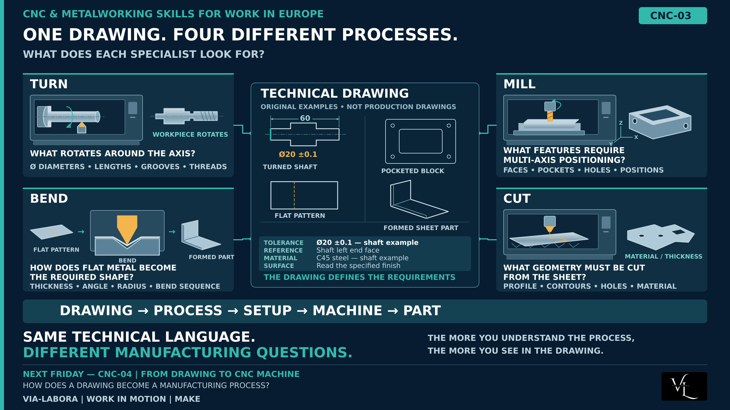
View original board full size (opens a new tab) ↗
The board combines separate teaching examples, not one component to be manufactured by all four processes. Its milling reference to ‘multi-axis positioning’ does not mean that four- or five-axis machining is required. The drawings are illustrative and incomplete, not production documentation.
- Distinguish part requirements from manufacturing decisions.
- Ask process-specific questions for turning, milling, bending and laser cutting.
- Recognise missing information and handover requirements.
Why this matters at work
Recognising a dimension is only the beginning.
A diameter may describe a turned surface, a drilled hole, or an opening cut from sheet. The symbol alone does not prescribe the manufacturing method.
Similarly, a finished bracket drawing does not automatically provide a production-ready flat pattern, and a pocket outline does not explain how a cutter can reach every surface.
Understanding the process helps you:
- Ask better questions before production.
- Recognise which requirements affect your operation.
- Identify where another operation may be needed.
- Avoid assuming that visible geometry is the complete specification.
- Communicate with people working in other manufacturing areas.
- Recognise missing information before it becomes a production problem.
Learning objectives
By the end of this lesson, you should be able to:
- Explain the difference between a part requirement and a manufacturing decision.
- Identify typical drawing questions for TURN, MILL, BEND, and CUT.
- Explain why similar features may require different process considerations.
- Recognise when a final-part drawing is insufficient for a particular operation.
- Distinguish finished geometry, starting material, and intermediate geometry.
- Describe a basic handover between cutting and bending.
- Identify information that must be clarified rather than guessed.
Prerequisites
Recommended previous lessons:
CNC-01 — ONE INDUSTRY. DIFFERENT CNC CAREERS.
CNC-02 — READ THE DRAWING BEFORE YOU START.
You should recognise basic dimensions, tolerances, references, and additional drawing requirements.
You do not need to calculate cutting data, develop a flat pattern, choose tooling, or write a CNC program.
Core theory
The requirement and the method are different
A requirement describes what must be achieved.
A manufacturing decision concerns how the work will be performed.
| Requirement | Manufacturing question |
|---|---|
| A specified diameter and tolerance | Which operation can produce and verify it? |
| A pocket with a specified depth | How can the feature be accessed and machined? |
| A finished bend angle and radius | What forming method and tooling can achieve them? |
| A sheet-metal profile | How will it be cut while meeting the applicable requirements? |
Some documentation specifies or restricts the manufacturing method. Always follow those requirements.
Where the method is not prescribed, it still needs to be selected and validated by the responsible people. The operator should not independently redesign the process outside their authority.
Start with shared information
All four pathways need a reliable starting point:
- Correct part and approved revision.
- Applicable drawing, model, and supporting documents.
- Units.
- Material specification and condition.
- Geometry and tolerances.
- Relevant references.
- Surface and finishing requirements.
- The scope of the current operation.
Process specialists emphasise different questions, but no specialist is free to ignore an applicable requirement.
APPROVED PART REQUIREMENTS
Rotational features and axial relationships.
Feature access and positions.
Flat-to-formed geometry.
Contours and operation scope.
Four process perspectives on requirements. The same component does not necessarily use all four processes.
TURN — what relates to the rotational axis?
The board asks:
WHAT ROTATES AROUND THE AXIS?
For conventional turning, examine rotational features and their relationships.
Typical questions include:
- Which surfaces are cylindrical?
- Which diameters and lengths are specified?
- Where are the shoulders, grooves, or threads?
- How are axial positions defined?
- Which surface requirements apply?
- Are additional non-rotational features present?
- What requirements apply between features produced in different operations?
A round-looking component is not automatically a turning-only job.
A shaft may also require flats, cross-holes, or other features produced through additional capabilities or operations.
MILL — which features must be reached and positioned?
The board highlights:
FACES • POCKETS • HOLES • POSITIONS
A milling specialist considers the geometry and accessibility of the features.
Typical questions include:
- Which faces need machining?
- What are the pocket dimensions and depth?
- Which holes require drilling, threading, or another operation?
- From which references are features located?
- Can the required surfaces be reached?
- Are there internal corner-radius requirements?
- Might more than one orientation or setup be necessary?
A conventional cylindrical end mill leaves a radius in an internal plan-view corner. A requirement for a sharp internal corner cannot simply be assumed achievable by the same ordinary milling operation.
Do not alter the part to suit an available cutter without approval.
The board uses the phrase “multi-axis positioning”. Here, it refers broadly to controlled positioning in space. It does not establish a requirement for a four- or five-axis machine.
Many faces, pockets, and holes can be produced on a suitable three-axis machine. The complete geometry, access, accuracy, and process plan determine the required capabilities.
BEND — how does the flat blank become the required shape?
The board asks:
HOW DOES FLAT METAL BECOME THE REQUIRED SHAPE?
A bending specialist considers the relationship between the starting blank and the finished part.
Typical questions include:
- What material and thickness are specified?
- Which dimensions describe the finished part?
- What angles and inside radii are required?
- Is an approved flat pattern available?
- Which bend directions and orientations apply?
- Can the part be formed without interference?
- What bending sequence is feasible?
- Which dimensions must be checked after forming?
Finished flange dimensions must not simply be added together to determine blank size.
The bend region and material behaviour affect the developed geometry. Flat-pattern development requires appropriate process data and responsibility.
This lesson identifies that relationship. It does not teach bend-allowance calculations or tool selection.
CUT — what geometry must be separated from the sheet?
The board asks:
WHAT GEOMETRY MUST BE CUT FROM THE SHEET?
In this series, CUT initially focuses on CNC laser cutting of sheet metal.
Typical questions include:
- Is the approved geometry for a flat finished part or an intermediate blank?
- Which external and internal contours must be cut?
- What material and thickness apply?
- Are the units and revision consistent across the drawing and cutting file?
- Which dimensions and edge requirements apply?
- Are some holes or other features completed later?
- Is part identification or orientation important for the next operation?
- Can the specified geometry be produced within the validated process capability?
A CAD contour file can carry useful geometry while omitting material, tolerances, finishing notes, and other requirements.
A cutting file should not automatically be treated as a complete replacement for the drawing and job documentation.
The drawn contour is also different from the machine’s compensated cutting path. How that path is generated belongs to later process and programming lessons.
One feature can raise several questions
Consider a hole.
The drawing may specify its diameter, position, depth, thread, surface requirements, and other characteristics.
A milling specialist may consider drilling and finishing operations.
A laser-cutting specialist may need to establish whether it is a cut opening or a feature intended for later machining.
A bending specialist may need to consider how its position relates to the finished geometry and forming operation.
The requirement remains the requirement. Each process contributes different questions about achieving it.
Starting material, intermediate geometry, and finished geometry
These are different stages:
STARTING MATERIAL:
The material supplied before an operation.
INTERMEDIATE GEOMETRY:
The condition of the part between operations.
FINISHED GEOMETRY:
The condition required after the defined manufacturing scope is complete.
For a simple sheet-metal bracket:
Sheet → cut blank → bent bracket.
The cutting operation may produce a correct blank even though the bracket is not yet finished.
Conversely, a blank with the wrong developed geometry can create problems during bending even if its outline matches an incorrect cutting file.
The documents and checks must match the stage of manufacture.
Simplified sequence — not production documentation.
Does the blank match the approved cutting requirements?
Does the formed part meet the finished requirements?
A drawing does not uniquely determine the full process route
Material, quantity, available equipment, accessibility, tolerances, and other constraints affect planning.
The board’s sequence:
DRAWING → PROCESS → SETUP → MACHINE → PART
is an introductory manufacturing sequence.
Inspection, verification, and feedback also belong to the work. They are not optional simply because the compact graphic does not show every step.
CNC-04 will develop the journey from requirements to an executable manufacturing plan.
Technical terminology
| Term | Meaning |
|---|---|
| Requirement | A condition the part or operation must satisfy |
| Process route | Planned sequence of manufacturing operations |
| Feature | A defined element of the part, such as a face, hole, pocket, or groove |
| Rotational feature | Geometry associated with rotation around an axis |
| Shoulder | A transition between different sections, commonly seen on shafts |
| A recessed region produced within a part | |
| Tool access | Ability to reach a feature with suitable tooling |
| Internal corner radius | Radius where internal boundaries meet |
| Flat pattern | Developed geometry of a sheet-metal part before forming |
| Blank | Starting or intermediate piece prepared for an operation |
| Flange | A projecting section of a formed sheet-metal part |
| Bend sequence | Order in which bends are made |
| Contour | Boundary defining a profile or opening |
| Kerf | Width of material removed by a cutting process |
| Intermediate part | A component awaiting further operations |
| Handover | Transfer of the part and relevant information to the next person or operation |
Step-by-step: turn drawing information into useful questions
Step 1 — Confirm the shared requirements
Check the part, revision, units, material, dimensions, and additional requirements.
Use the CNC-02 drawing checklist.
Step 2 — Identify the geometry
Recognise rotational surfaces, faces, pockets, holes, bends, and profiles.
Do not select a process solely from one symbol.
Step 3 — Identify the operation’s scope
Are you producing a finished feature, an intermediate blank, or only part of the geometry?
Step 4 — Ask the process-specific questions
TURN:
What relates to the rotational axis?
MILL:
Which features need access and controlled positioning?
BEND:
How does the flat blank become the finished shape?
CUT:
Which contours must be separated from the sheet?
Step 5 — Identify relationships between operations
Which information and geometry must remain consistent through the handover?
Step 6 — Record unresolved issues
Examples include an undefined hole, missing radius, unclear material condition, inconsistent revision, or unavailable approved flat pattern.
Step 7 — Escalate decisions outside your scope
Raise a specific question with the responsible person.
Do not resolve a missing engineering requirement through an unapproved machine adjustment.
Process-specific examples
TURN — a stepped shaft
The board shows a shaft example with an overall-length indication of 60 and a separate Ø20 ±0.1 example.
For this lesson, interpret Ø20 ±0.1 as a sample diameter requirement:
Lower limit: 19.9 mm.
Upper limit: 20.1 mm.
The board does not attach that callout to a specific shaft step through complete dimensioning. Do not guess which segment it controls.
Its C45 material note is also an example, not a complete procurement specification including all required condition or treatment information.
A production job needs the approved complete documentation.
MILL — a pocketed block
A block includes a recessed pocket and holes.
The milling specialist checks the pocket dimensions, depth, corner radii, hole requirements, positions, and references.
The board does not supply those complete requirements.
A three-dimensional illustration helps recognise the form, but it does not replace the missing dimensions.
BEND — a simple bracket
A flat blank is formed into an L-shaped bracket.
The bending specialist needs the material, thickness, finished geometry, bend requirements, and approved process information.
The flat pattern must correspond to that same bracket. It cannot be obtained by visually flattening the illustration or adding flange lengths without the required development data.
CUT — a flat profile
A laser cutting operation produces an external profile and internal openings.
The specialist checks the approved contour, material, thickness, applicable tolerances, and requirements for the cut edges.
If a hole requires subsequent machining, the route and intermediate requirements must define what the cutting operation should produce.
Common mistakes
| Mistake | Better understanding |
|---|---|
| “One drawing means one part must use all four processes.” | The lesson compares four ways of interpreting technical information. |
| “A diameter symbol means the feature must be turned.” | A diameter describes geometry; it does not automatically prescribe a method. |
| “Every pocket requires five-axis machining.” | Required capability depends on the complete geometry and access. |
| “The visible pocket outline defines its depth.” | Depth needs a stated requirement or approved source data. |
| “A finished bracket drawing is already a flat pattern.” | Developed geometry requires appropriate process information. |
| “The cutting file contains every requirement.” | Other documents may define material, tolerances, finishing, and operation scope. |
| “A good blank proves the finished bracket is correct.” | Later operations introduce additional requirements and checks. |
| “I can change the radius because our cutter is larger.” | Changes to requirements need approval. |
| “Inspection starts only when all manufacturing is finished.” | Verification is planned at the relevant stages. |
Operator / Setter / Programmer perspective
OPERATOR
Identify the requirements relevant to the current operation, perform assigned checks, and report unclear information or deviations.
SETTER
Consider how the planned setup supports access, feature relationships, and verification.
PROGRAMMER
Translate the approved process plan and source data into instructions for the specified machine. Identify missing or infeasible information rather than inventing requirements.
These roles may overlap. The workplace defines who approves the route, resolves engineering questions, and releases production.
Real job context
A blank passes cutting but fails at bending
A laser-cut blank matches the cutting file. During bending, the finished flange dimension does not meet the approved part requirement.
It would be premature to assume that the bending operator caused the problem.
The responsible team may need to check:
- Whether the drawing and flat pattern use consistent revisions.
- Whether the approved developed geometry was used.
- Material and thickness.
- The actual blank.
- Tooling and bending method.
- Orientation and sequence.
- Measurement method.
The purpose is to locate the cause using evidence.
An operator should report what was observed and follow the workplace procedure. Arbitrarily changing the blank or bending settings can hide the cause and create another problem.
Try it yourself
Exercise 1 — Ask the specialist
Match each question to its primary pathway.
A. Are these finished flange dimensions or approved flat-pattern dimensions?
B. Which diameters and axial lengths are required?
C. Is this opening completed by cutting or finished in a later operation?
D. Can the tool reach the pocket, and what internal corner radius is specified?
Show suggested answer
A: BEND.
B: TURN.
C: CUT.
D: MILL.
These are primary associations, not exclusive ownership of the information.
Exercise 2 — Four separate teaching briefs
These are fictional VIA-LABORA examples, not production instructions.
- A shaft requires a specified cylindrical diameter and a shoulder position.
- A block requires a blind pocket, but the available sketch omits pocket depth.
- A finished bracket is dimensioned, but no approved flat pattern is available.
- A cutting file is available, but its revision cannot be matched to the job drawing.
For each brief, write:
- The primary process question.
- The missing or critical information.
- One action that would be inappropriate without approval.
Show suggested answer
- TURN: establish the controlled surfaces and axial references. Do not choose missing tolerances or reference relationships.
- MILL: obtain the required depth and other missing pocket requirements. Do not select depth from the illustration.
- BEND / process preparation: obtain or develop the approved flat pattern through the responsible process. Do not simply add finished flange dimensions.
- CUT: confirm approved geometry and revision consistency. Do not assume the cutting file is correct because it opens successfully.
Exercise 3 — Read the anchor critically
Can the social board alone tell you:
- Which shaft step carries the Ø20 ±0.1 requirement?
- The pocket depth?
- The exact developed length of the bracket blank?
- The permitted edge condition for the cut profile?
Show suggested answer
No. These details are not fully specified.
The board teaches questions and relationships. It does not provide a complete manufacturing package.
Exercise 4 — Write a handover
Prepare a short cutting-to-bending handover outline.
Include:
- Part and job identification.
- Drawing and flat-pattern revisions.
- Material and thickness.
- Quantity and identification of the blanks.
- Applicable inspection status.
- Orientation or surface information where required.
- Any unresolved issue.
Use approved workplace documents. Do not create an alternative uncontrolled production record.
Knowledge check
1. Does a drawing always define one unique manufacturing route?
Show answer and explanation
No. The route also depends on constraints and approved planning decisions, unless methods are prescribed.
2. Does a diameter callout automatically mean turning?
Show answer and explanation
No. It defines circular geometry; several processes can contribute to producing it.
3. Does the phrase “multi-axis positioning” prove that a five-axis machine is required?
Show answer and explanation
No. Machine capability must be determined from the actual job.
4. Can finished flange dimensions simply be added to obtain flat-pattern length?
Show answer and explanation
No. The bend region and process data must be considered.
5. Does an approved cutting contour automatically specify every material and quality requirement?
Show answer and explanation
No. The full job documentation must be checked.
6. What are the simple dimensional limits for Ø20 ±0.1 mm?
Show answer and explanation
19.9 mm and 20.1 mm. Actual conformity decisions require the approved measurement process.
7. Does a correct intermediate blank guarantee a conforming finished part?
Show answer and explanation
No. Later operations and final requirements must also be verified.
8. What should you do when the necessary process information is missing?
Show answer and explanation
Record the specific gap and obtain clarification through the responsible person.
Key takeaways
- The drawing defines requirements; the process plan defines how the work will be carried out.
- The same technical language raises different manufacturing questions.
- TURN focuses attention on rotational features and axial relationships.
- MILL raises questions about features, access, and positions.
- BEND connects flat geometry with the finished shape.
- CUT focuses on the required sheet contours and the scope of the cutting operation.
- A part may require several processes.
- Intermediate and finished geometry must not be confused.
- The more you understand the process, the more you see in the drawing.
Four-Process Drawing Question Map
Shared requirements
TURN
Diameters / lengths / shoulders / grooves / threads / axial relationships.
MILL
Faces / pockets / depth / holes / positions / access / corner requirements.
BEND
Material / thickness / finished geometry / approved flat pattern / bend requirements / sequence feasibility.
CUT
External and internal contours / material / thickness / file revision / edge requirements / later operations.
Handover
Further reading
Manufacturer resources for additional process context:
These resources do not replace the approved documents and instructions for a specific job.
Next in the series
CNC-04 — From Drawing to CNC Machine connects requirements with a planned manufacturing sequence and the preparation needed before machine execution.
Additional English lesson overview
SAME TECHNICAL LANGUAGE. DIFFERENT MANUFACTURING QUESTIONS.
Turning, milling, bending, and cutting specialists read dimensions, tolerances, material information, and references.
They then ask different questions about achieving those requirements.
“One drawing” means a shared technical language. It does not mean one identical component must be made by all four processes.
Situation from Work
A laser-cut blank matches its cutting file, but the bent bracket does not meet the finished flange requirement.
The team must investigate the relationship between the drawing, developed blank, material, forming method, and inspection.
Blaming one operation before checking the evidence can lead to the wrong correction.
Who Is This For?
Operators, setters, programmers, technologists, candidates, and team leaders working across process boundaries.
Recommended previous lesson: CNC-02.
What Will You Gain?
You will learn to turn drawing information into process-specific questions and identify what the next operation needs.
Learning Objectives
You should be able to:
- Separate a requirement from a manufacturing decision.
- Ask relevant TURN, MILL, BEND, and CUT questions.
- Distinguish starting, intermediate, and finished geometry.
- Recognise missing process information.
- Prepare a useful operation handover.
Technical Foundation
Requirements and methods
The drawing specifies what must be achieved. The process plan defines how the work is organised.
Methods may also be prescribed or restricted by documentation. Follow those requirements.
A diameter symbol describes geometry. It does not automatically prescribe turning.
Shared starting point
Confirm the part, revision, units, material, dimensions, tolerances, references, additional requirements, and operation scope.
TURN — what relates to the rotational axis?
Look for diameters, axial lengths, shoulders, grooves, threads, bores, and relevant surface requirements.
A shaft may also contain flats or cross-holes requiring additional capabilities or operations.
MILL — which features need access and positioning?
Look for faces, pockets, depths, holes, positions, and internal corner requirements.
An ordinary cylindrical end mill leaves a radius at an internal plan-view corner. Do not change a required corner to suit available tooling without approval.
Many pockets and holes can be produced on a suitable three-axis machine. Actual geometry and access determine the required capability.
BEND — how does the blank become the finished shape?
Check material, thickness, finished dimensions, angles, radii, approved flat pattern, orientation, and sequence feasibility.
Do not obtain blank length by simply adding finished flange dimensions. The bend region and appropriate development data matter.
CUT — which contours must be separated?
Check approved geometry, material, thickness, file revision, edge requirements, and later operations.
A contour file may omit requirements contained in the drawing and job documents.
The part contour and compensated machine cutting path are different concepts.
Terminology EN / PL
| English | Polski |
|---|---|
| Requirement | Wymaganie |
| Process route | Droga technologiczna |
| Feature | Cecha / element geometryczny |
| Shoulder | Stopień / odsadzenie |
| Kieszeń | |
| Tool access | Dostęp narzędzia |
| Flat pattern | Rozwinięcie |
| Blank | Wykrojka / półfabrykat |
| Flange | Kołnierz / ścianka po gięciu |
| Bend sequence | Kolejność gięć |
| Contour | Kontur |
| Kerf | Szerokość szczeliny cięcia |
| Intermediate geometry | Geometria międzyoperacyjna |
| Handover | Przekazanie pracy |
Process Explanation
- Confirm shared requirements.
- Identify the features.
- Establish the current operation’s scope.
- Ask process-specific questions.
- Identify relationships with other operations.
- Record missing information.
- Obtain clarification within the responsibility system.
APPROVED PART REQUIREMENTS
Rotational features and axial relationships.
Feature access and positions.
Flat-to-formed geometry.
Contours and operation scope.
Four process perspectives on requirements. The same component does not necessarily use all four processes.
Starting material, intermediate part, and finished part are different stages.
A typical bracket sequence is:
SHEET → CUT BLANK → BENT BRACKET.
Checks must suit the stage. A correct blank does not prove the finished bracket will conform.
Simplified sequence — not production documentation.
Does the blank match the approved cutting requirements?
Does the formed part meet the finished requirements?
Worked Example
A finished bracket drawing is available. A cutting file has a different revision identifier, and its approved relationship to the drawing is unknown.
- Identify the unresolved compatibility.
- Do not cut merely because the file opens.
- Ask the responsible person to confirm the approved developed geometry.
- Confirm material and operation information.
- Use the approved package for cutting and subsequent bending.
- Verify the blank and formed result as required.
Different identifiers may be compatible, but that relationship needs confirmation.
The social board’s Ø20 ±0.1 example gives simple limits of 19.9–20.1 mm. Its incomplete attachment does not establish which shaft step it controls.
Control / Process Differences
TURN, MILL, BEND, and CUT are process pathways.
FANUC, SINUMERIK, HEIDENHAIN, and MAZATROL identify control systems or families.
A control brand does not determine the complete route or remove process constraints.
Machine configuration, tooling, access, material, and requirements matter.
Common Mistakes
- Treating the board as one universal component.
- Assuming every diameter must be turned.
- Assuming every pocket needs five axes.
- Guessing pocket depth from an illustration.
- Treating the finished bracket drawing as a flat pattern.
- Treating the cutting file as the complete specification.
- Assuming a correct intermediate part proves final conformity.
- Altering a feature to suit available tooling without approval.
Safety and Authorisation
Operators perform assigned work and checks. Setters prepare setups. Programmers prepare instructions. Technologists develop the route within their responsibility. Service technicians address equipment issues.
Roles may overlap. Do not invent missing requirements or change the route outside your authority.
Do not manufacture from the teaching board.
Practical Exercise
Match the question to its primary pathway:
A. Which diameters and axial lengths are required?
B. Is pocket depth specified, and can the tool reach it?
C. Is this a finished dimension or developed-blank dimension?
D. Is this opening completed by cutting or machined later?
Show answers
A TURN; B MILL; C BEND; D CUT.
Then identify what the board does not fully specify:
- Which shaft step carries Ø20 ±0.1.
- Pocket depth.
- Developed blank length.
- Permitted cut-edge condition.
The correct response is to recognise the gaps.
Knowledge Check
Does a drawing always define one unique route?
Show answer
No.
Does Ø automatically mean turning?
Show answer
No.
Does “multi-axis” prove five-axis equipment is required?
Show answer
No.
Can flange lengths simply be added for blank length?
Show answer
No.
Can a cutting file omit requirements?
Show answer
Yes.
Does a correct blank guarantee the finished part?
Show answer
No.
What should missing information trigger?
Show answer
A specific clarification request.
Use It in a Technical Interview
“I identify the requirements relevant to my operation and check what must be completed now or later. I compare the approved geometry and revision information and raise missing details rather than guessing.”
Add a real example from your process.
Use It With Your Team
At a handover, confirm part identity, document relationships, material, operation scope, inspection status, orientation where relevant, and unresolved issues.
Use controlled workplace records.
Key Takeaways
- Requirements and manufacturing decisions are different.
- Process knowledge reveals different questions.
- Shared information matters across all four pathways.
- Intermediate and finished geometry must be distinguished.
- A drawing or contour file may not contain the complete operation package.
- Better questions prevent unsupported assumptions.
Worksheet overview
FOUR-PROCESS DRAWING QUESTION MAP
Header: job, part, drawing/revision, operation, reviewer/date.
Shared checks: documents, units, material, dimensions, tolerances, references, additional requirements, operation scope.
Four panels:
TURN — diameters, lengths, shoulders, grooves, threads.
MILL — faces, pockets, depth, holes, access, positions.
BEND — thickness, finished geometry, flat pattern, bends, sequence.
CUT — contours, thickness, file revision, edges, later operations.
For each panel:
Relevant requirements:
Missing information:
Question / responsible person:
Handover:
What must the next operation receive?
What has been verified?
What remains unresolved?
CNC-03 — Jeden język rysunku. Cztery różne procesy.
TEN SAM JĘZYK TECHNICZNY. RÓŻNE PYTANIA PRODUKCYJNE.
Specjaliści toczenia, frezowania, gięcia i cięcia odczytują wymiary, tolerancje, materiał oraz odniesienia.
Następnie zadają różne pytania o sposób osiągnięcia wymagań.
„Jeden rysunek” oznacza wspólny język dokumentacji. Nie oznacza jednego detalu wykonywanego wszystkimi procesami.
Sytuacja z pracy
Wykrojka odpowiada plikowi cięcia, lecz po gięciu wspornik nie spełnia wymiaru ścianki.
Trzeba sprawdzić relację rysunku, rozwinięcia, materiału, metody gięcia i kontroli.
Przypisanie winy jednej operacji przed analizą może prowadzić do błędnej korekty.
Dla kogo jest ta lekcja?
Dla operatorów, ustawiaczy, programistów, technologów, kandydatów i liderów współpracujących między procesami.
Zalecana lekcja wcześniejsza: CNC-02.
Co zyskasz?
Nauczysz się zamieniać wymagania rysunkowe w pytania procesowe i ustalać potrzeby kolejnej operacji.
Cele nauki
Po lekcji potrafisz:
- Oddzielić wymaganie od decyzji wykonawczej.
- Zadawać pytania TURN, MILL, BEND i CUT.
- Rozróżniać materiał wyjściowy, geometrię międzyoperacyjną i gotową.
- Wskazywać braki.
- Przygotować przekazanie operacji.
Podstawy techniczne
Wymaganie i metoda
Rysunek określa wymagany rezultat. Plan procesu organizuje wykonanie.
Dokumentacja może również narzucać lub ograniczać metody. Trzeba ich przestrzegać.
Symbol średnicy określa geometrię, nie automatycznie toczenie.
Wspólna podstawa
Potwierdź część, rewizję, jednostki, materiał, wymiary, tolerancje, odniesienia, wymagania dodatkowe i zakres operacji.
TURN — co odnosi się do osi obrotu?
Sprawdź średnice, długości osiowe, stopnie, rowki, gwinty, otwory i powierzchnie.
Wałek może zawierać płaskie powierzchnie lub otwory poprzeczne wymagające dodatkowych możliwości albo operacji.
MILL — jakie cechy wymagają dostępu i pozycjonowania?
Sprawdź powierzchnie, kieszenie, głębokości, otwory, położenia i naroża.
Zwykły frez walcowy pozostawia promień w wewnętrznym narożu konturu. Nie zmieniaj wymagania pod dostępne narzędzie bez zgody.
Wiele kieszeni i otworów można wykonać na odpowiedniej maszynie 3-osiowej. Decydują pełna geometria i dostęp.
BEND — jak wykrojka staje się gotowym kształtem?
Sprawdź materiał, grubość, gotowe wymiary, kąty, promienie, rozwinięcie, orientację i wykonalność sekwencji.
Nie obliczaj wykrojki przez proste dodanie wymiarów ścianek. Znaczenie mają strefa gięcia i właściwe dane rozwinięcia.
CUT — jakie kontury rozdzielamy?
Sprawdź geometrię, materiał, grubość, wersję pliku, krawędzie i dalsze operacje.
Plik konturu może nie zawierać wymagań rysunku i zlecenia.
Kontur części oraz skompensowana ścieżka maszyny to różne pojęcia.
Terminologia EN / PL
| English | Polski |
|---|---|
| Requirement | Wymaganie |
| Process route | Droga technologiczna |
| Feature | Cecha / element geometryczny |
| Shoulder | Stopień / odsadzenie |
| Kieszeń | |
| Tool access | Dostęp narzędzia |
| Flat pattern | Rozwinięcie |
| Blank | Wykrojka / półfabrykat |
| Flange | Kołnierz / ścianka po gięciu |
| Bend sequence | Kolejność gięć |
| Contour | Kontur |
| Kerf | Szerokość szczeliny cięcia |
| Intermediate geometry | Geometria międzyoperacyjna |
| Handover | Przekazanie pracy |
Wyjaśnienie procesu
- Potwierdź wymagania.
- Rozpoznaj cechy.
- Ustal zakres operacji.
- Zadaj pytania procesowe.
- Określ powiązania z kolejnymi operacjami.
- Zapisz braki.
- Uzyskaj wyjaśnienie od odpowiedzialnej osoby.
ZATWIERDZONE WYMAGANIA
Cechy obrotowe i relacje osiowe.
Dostęp do cech i ich położenia.
Od geometrii płaskiej do gotowego kształtu.
Kontury i zakres operacji.
Cztery perspektywy procesowe; ten sam detal nie musi wymagać wszystkich czterech procesów.
Materiał wyjściowy, półprodukt i gotowa część to różne etapy.
Przykład:
ARKUSZ → WYKROJKA → ZGIĘTY WSPORNIK.
Kontrole muszą odpowiadać etapowi. Poprawna wykrojka nie dowodzi zgodności gotowego wspornika.
Uproszczony przebieg — nie dokumentacja produkcyjna.
Czy wykrojka spełnia zatwierdzone wymagania cięcia?
Czy zgięta część spełnia wymagania końcowe?
Przykład z rozwiązaniem
Dostępny jest rysunek wspornika. Plik cięcia ma inne oznaczenie wersji, a jego zgodność z rysunkiem nie została potwierdzona.
- Rozpoznaj brak potwierdzenia.
- Nie rozpoczynaj tylko dlatego, że plik się otwiera.
- Uzyskaj potwierdzenie zatwierdzonego rozwinięcia.
- Potwierdź materiał i informacje operacyjne.
- Użyj właściwego pakietu do cięcia i gięcia.
- Sprawdź wykrojkę i gotowy rezultat.
Różne oznaczenia mogą być zgodne, lecz trzeba potwierdzić ich powiązanie.
Przykład Ø20 ±0,1 daje granice 19,9–20,1 mm. Plansza nie określa jednoznacznie kontrolowanego stopnia wałka.
Różnice procesów i sterowań
TURN, MILL, BEND i CUT to procesy.
FANUC, SINUMERIK, HEIDENHAIN i MAZATROL to sterowania lub ich rodziny.
Marka sterowania nie określa całej technologii i nie usuwa ograniczeń procesu.
Znaczenie mają konfiguracja, narzędzia, dostęp, materiał i wymagania.
Typowe błędy
- Traktowanie planszy jako jednego uniwersalnego detalu.
- Przypisywanie każdej średnicy do toczenia.
- Zakładanie pięciu osi dla każdej kieszeni.
- Zgadywanie głębokości z obrazu.
- Uznawanie rysunku gotowego wspornika za rozwinięcie.
- Traktowanie pliku cięcia jako pełnej specyfikacji.
- Uznawanie półproduktu za dowód zgodności końcowej.
- Zmienianie cechy pod narzędzie bez zgody.
Bezpieczeństwo i uprawnienia
Operator wykonuje zadania i kontrole. Ustawiacz przygotowuje ustawienie. Programista przygotowuje instrukcje. Technolog opracowuje drogę wykonania. Serwisant zajmuje się wyposażeniem.
Role mogą się łączyć. Nie wymyślaj brakujących wymagań i nie zmieniaj technologii poza swoim zakresem.
Nie produkuj na podstawie planszy dydaktycznej.
Ćwiczenie praktyczne
Przyporządkuj pytanie:
A. Jakie średnice i długości osiowe?
B. Jaka głębokość kieszeni i dostęp?
C. Wymiar gotowy czy rozwinięcia?
D. Otwór wycinany czy obrabiany później?
Pokaż odpowiedzi
A TURN; B MILL; C BEND; D CUT.
Wskaż braki planszy: przypisanie Ø20 ±0,1, głębokość kieszeni, długość rozwinięcia, dopuszczalny stan krawędzi.
Prawidłową odpowiedzią jest rozpoznanie braków.
Sprawdzenie wiedzy
Czy rysunek zawsze narzuca jedną drogę?
Pokaż odpowiedź
Nie.
Czy Ø oznacza toczenie?
Pokaż odpowiedź
Nie.
Czy „multi-axis” dowodzi potrzeby pięciu osi?
Pokaż odpowiedź
Nie.
Czy wystarczy dodać ścianki, aby dostać rozwinięcie?
Pokaż odpowiedź
Nie.
Czy plik cięcia może pomijać wymagania?
Pokaż odpowiedź
Tak.
Czy dobra wykrojka gwarantuje detal końcowy?
Pokaż odpowiedź
Nie.
Co zrobić z brakami?
Pokaż odpowiedź
Zadać konkretne pytanie odpowiedzialnej osobie.
Wykorzystaj na rozmowie technicznej
„Rozpoznaję wymagania mojej operacji i ustalam, co wykonujemy teraz, a co później. Sprawdzam zatwierdzoną geometrię i wersje. Braki zgłaszam zamiast zgadywać”.
Dodaj rzeczywisty przykład.
Wykorzystaj z zespołem
Potwierdźcie identyfikację, powiązania dokumentów, materiał, zakres, stan kontroli, orientację i problemy.
Korzystajcie z nadzorowanych zapisów.
Najważniejsze wnioski
- Wymaganie i decyzja technologiczna są różne.
- Wiedza procesowa ujawnia różne pytania.
- Wspólne informacje dotyczą wszystkich ścieżek.
- Rozdzielaj geometrię międzyoperacyjną i gotową.
- Rysunek lub plik konturu może nie stanowić pełnego pakietu.
- Konkretne pytania ograniczają nieuzasadnione założenia.
Mapa pytań — materiał pomocniczy
MAPA PYTAŃ RYSUNKOWYCH CZTERECH PROCESÓW
Nagłówek: zlecenie, część, rysunek/rewizja, operacja, osoba/data.
Sprawdzenia wspólne: dokumenty, jednostki, materiał, wymiary, tolerancje, odniesienia, uwagi i zakres.
TURN — średnice, długości, stopnie, rowki, gwinty.
MILL — powierzchnie, kieszenie, głębokość, otwory, dostęp, pozycje.
BEND — grubość, gotowy kształt, rozwinięcie, gięcia, kolejność.
CUT — kontury, grubość, wersja pliku, krawędzie, dalsze operacje.
Dla każdego panelu:
Wymagania:
Braki:
Pytanie / osoba odpowiedzialna:
Przekazanie:
Co otrzymuje następna operacja?
Co sprawdzono?
Co pozostaje otwarte?