Don’t start with the machine. Start with the drawing.
Before asking which tool to use or which program to run, establish what the finished part must satisfy.
A technical drawing can communicate size, permitted variation, feature locations, material, surface requirements, and other information needed to manufacture and inspect a part.
Reading only the largest dimensions is not enough.
In CNC-01, we separated manufacturing processes from machines, controls, and responsibilities. This lesson introduces the information those different roles need to understand before work begins.
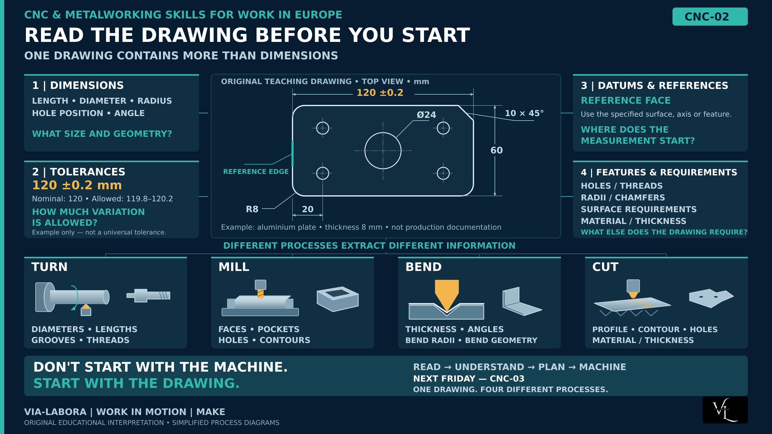
View full-size graphic (opens a new tab) ↗
One drawing contains more than dimensions. Read the sizes, permitted variation, references, and additional requirements before planning the work.
Teaching example, not production documentation. The highlighted reference edge is illustrative, not a formal datum designation or an instruction for setting CNC work zero. The four process panels show different applications of drawing knowledge; they are not four required ways to manufacture the illustrated plate.
- Identify revisions and drawing requirements
- Calculate simple specification limits
- Recognise references and clarify missing information
Why this matters at work
A machine can repeat a programmed operation consistently while producing the wrong result.
The wrong drawing revision, an overlooked tolerance, an incorrect material, or a misunderstood reference can affect an entire production batch.
Reading the requirements first helps prevent:
- Making an outdated version of a part.
- Producing the correct nominal size with unacceptable variation.
- Locating a feature from the wrong reference.
- Missing a thread, chamfer, finish, or material requirement.
- Inspecting a feature using an unsuitable interpretation.
- Treating incomplete information as permission to guess.
The drawing is an important source of requirements. It must be read together with applicable models, specifications, job documents, and workplace instructions. If they conflict, obtain clarification through the responsible person.
Learning objectives
By the end of this lesson, you should be able to:
- Identify the part, drawing revision, units, and relevant views.
- Distinguish a nominal dimension from its permitted variation.
- Calculate simple upper and lower limits.
- Recognise common feature information such as diameters, radii, and chamfers.
- Explain why references matter.
- Distinguish an illustrative reference from a formal datum and CNC work zero.
- Identify missing information without inventing requirements.
- Build a basic drawing-review checklist.
Prerequisites
Recommended previous lesson:
CNC-01 — ONE INDUSTRY. DIFFERENT CNC CAREERS.
You should understand the basic differences between TURN, MILL, BEND, and CUT.
Basic arithmetic with decimal numbers is useful.
This lesson introduces drawing interpretation. It does not teach complete geometrical tolerancing, inspection planning, process planning, or machine setup.
Core theory
1. Confirm which document applies
Before interpreting a dimension, confirm the document.
Check:
- Part or drawing number.
- Revision and release status.
- Relevant sheet numbers.
- Units.
- Material information.
- General notes.
- Referenced specifications and documents.
Use the approved document identified by the job and document-control process. A file with the latest timestamp is not automatically the correct released revision.
If the job documents disagree, do not choose whichever version appears easier to manufacture.
2. Understand the views before interpreting features
A drawing may contain front, top, side, section, and detail views.
A circle in one view does not, by itself, establish every requirement for a hole. Other views and notes may define its depth, thread, counterbore, or other characteristics.
Check the indicated projection convention where relevant. Do not assume the arrangement of views.
Read the stated dimensions. Do not measure the displayed image to recover missing production dimensions.
Screenshots, print scaling, and browser resizing can change the apparent size.
3. Dimensions: what size and geometry?
A dimension identifies a specified size, distance, angle, or other dimensional requirement.
Examples include:
- Overall length.
- Hole diameter.
- Radius.
- Distance to a feature.
- Angle.
- Material thickness.
Common indications include:
- Ø — diameter.
- R — radius.
- An angular value expressed in degrees.
- A chamfer indication combining size and angle where specified.
Diameter and radius are different quantities.
In the teaching board:
- Ø24 identifies a nominal diameter of 24 mm for the indicated feature.
- R8 identifies the indicated radius of 8 mm.
- 120 ±0.2 mm gives a nominal length and explicit permitted variation.
- 10 × 45° identifies the illustrated chamfer requirement in its drawing context.
These are example requirements, not recommended values for other parts.
4. Tolerances: how much variation is allowed?
A nominal dimension gives the stated target size. A tolerance defines permitted variation.
For the example:
120 ±0.2 mm
Lower limit:
120 − 0.2 = 119.8 mm
Upper limit:
120 + 0.2 = 120.2 mm
Total tolerance width:
120.2 − 119.8 = 0.4 mm
The total width is 0.4 mm, not 0.2 mm.
A tolerance does not mean every feature on the drawing receives the same allowance.
Some requirements have individual tolerances. Others may be governed by general notes or explicitly referenced specifications.
If no applicable tolerance can be identified, do not invent one.
Tolerances can also be unequal, one-sided, or expressed through other systems. Their detailed interpretation belongs to later learning.
Specified limits describe an interval. Actual measurement decisions require the approved measurement method and decision rule.
5. Specification limits and measurement decisions
Calculating limits and deciding whether a measured part conforms are related but different tasks.
A measured value must be interpreted using the approved measurement method and decision rule. Measurement uncertainty can matter, especially near a limit.
This lesson uses arithmetic examples to explain specification limits. It does not establish a universal inspection acceptance rule.
6. References: where is the feature located?
A dimension needs a clear relationship to the features it describes.
For example, the board shows a 20 mm distance from the illustrated left-hand reference edge to the centreline of a hole.
Measuring from a different edge answers a different question.
A reference may involve a surface, axis, centre plane, or another defined feature, depending on the requirement.
However, three concepts must remain separate:
DRAWING REFERENCE:
The feature or relationship used to interpret the requirement.
FORMAL DATUM:
An ideal reference established from specified datum features according to the applicable geometrical specification rules.
CNC WORK ZERO:
A coordinate origin used in the machine setup and program.
These can be related through a properly planned setup, but they are not automatically identical.
The board’s highlighted edge is an introductory reference illustration. It does not formally designate a datum system or tell the operator where to set work zero.
Nominal geometry only — teaching example
Both distances refer to the same hole centreline; the chosen edge changes the distance being described.
7. Features and additional requirements
A drawing contains more than dimensions.
Check for:
- Hole quantities and types.
- Thread requirements.
- Blind or through features.
- Radii and chamfers.
- Surface texture requirements.
- Material grade and condition.
- Thickness.
- Coatings, treatments, or finishing notes.
- Geometrical requirements.
- Deburring or edge instructions.
- References to additional specifications.
A diameter callout alone does not establish that a hole is threaded.
A surface requirement does not automatically prescribe one particular manufacturing method.
“Aluminium” identifies a broad material family, not necessarily a complete material specification.
The teaching board intentionally omits information that a released production drawing may need. Its purpose is to teach what to look for, not to authorise manufacture.
Technical terminology
| Term | Meaning |
|---|---|
| Drawing number | Identifier for the drawing |
| Revision | Controlled version of a document |
| Title block | Area containing identification and other drawing information |
| View | Representation of the part from a specified direction or section |
| Nominal dimension | Stated dimension used to define a feature |
| Tolerance | Permitted variation associated with a requirement |
| Lower / upper limit | Boundaries of the specified dimensional interval |
| Diameter | Size across a circular feature through its centre |
| Radius | Distance from the centre of a circle or arc to its circumference |
| Chamfer | Bevelled edge feature |
| Reference | Defined feature or relationship used to interpret a requirement |
| Datum feature | Real feature identified for establishing a datum |
| Datum | Ideal reference established according to applicable specification rules |
| Work zero | Coordinate origin used for a machine setup and program |
| General tolerance | Tolerance applying within the scope of a stated general specification |
| Surface texture | Specified characteristics of a surface |
| Conformity | Fulfilment of specified requirements |
Step-by-step drawing review
Step 1 — Identify the part and approved revision
Match the drawing to the job.
Confirm the required release status and relevant sheets.
Step 2 — Confirm units and document conventions
Check units, view arrangement, and relevant drawing conventions.
Do not assume that the displayed scale can be used for measurement.
Step 3 — Build a picture of the part
Read the views, sections, and details together.
Identify which lines and callouts describe which features.
Step 4 — Find material and additional requirements
Read the title block, notes, and referenced documents.
Check whether the material specification and condition are sufficiently defined for the job.
Step 5 — Read dimensions and applicable tolerances
Separate nominal dimensions from permitted variation.
Identify individual tolerances and applicable general requirements.
Step 6 — Identify references
Establish which features define positions and relationships.
Do not substitute a convenient edge for the specified reference.
Step 7 — Identify what must be verified
List the relevant characteristics to inspect.
Detailed instrument selection and inspection methods require the approved inspection process and further training.
Step 8 — Resolve gaps before proceeding
Record missing or conflicting information.
Ask a specific question rather than filling the gap with an assumption.
Process-specific examples
These are separate examples showing how different specialists use drawing information. They do not describe four mandatory operations for the teaching plate.
TURN
For a turned shaft, the drawing may define diameters, lengths, shoulders, grooves, threads, and surface requirements.
The turning specialist needs to understand the required features and their relationships before considering the machining sequence.
MILL
For a milled plate, the drawing may define pocket geometry, hole locations, reference features, and surface requirements.
A hole with the correct diameter can still be in the wrong position.
BEND
For a bent bracket, relevant requirements may include material, thickness, finished angles, flange dimensions, and bend radii.
Finished-part dimensions must not automatically be treated as flat-pattern dimensions. Developing the blank requires process knowledge and appropriate bend data.
CUT
For a laser-cut blank, relevant requirements may include profile geometry, internal openings, material, thickness, edge requirements, and the scope of the cutting operation.
A hole shown in the final product may require another operation. Do not assume every final feature is completed by laser cutting.
Common mistakes
| Mistake | Better approach |
|---|---|
| Reading only the overall dimensions | Review notes, features, references, and additional requirements |
| Using an outdated drawing | Confirm the approved revision for the job |
| Measuring a screenshot | Use stated requirements and approved source data |
| Treating Ø and R as interchangeable | Identify diameter and radius correctly |
| Calling ±0.2 a total tolerance of 0.2 | Calculate the interval: total width is 0.4 |
| Applying one tolerance to every dimension | Check each requirement and applicable general notes |
| Treating a highlighted edge as a formal datum | Read the actual specification and datum indications |
| Treating a drawing reference as automatic work zero | Follow the planned setup and coordinate definition |
| Assuming all holes are through holes | Check views and callouts |
| Guessing missing material or hole information | Obtain clarification |
| Assuming a dimensionally correct feature proves the whole part conforms | Check all applicable requirements |
Operator / Setter / Programmer perspective
OPERATOR
Understand the requirements relevant to the assigned operation and inspection. Use the correct documents and report unclear or conflicting information.
SETTER
Understand how the required features and references relate to the planned workholding, accessibility, and verification.
PROGRAMMER
Use the approved requirements and source data to prepare instructions for the specified process and machine. Do not create missing engineering requirements through assumptions.
The same person may perform several roles. Responsibility for approving requirements and resolving drawing ambiguity must be defined by the workplace.
Real job context
A job pack identifies drawing revision B, but a printed drawing at the machine shows revision A.
The operator notices that a hole callout differs.
The correct response is to obtain the approved document through the workplace process and establish which instructions apply. The operator should not assume that either the printout or the newest-looking file is correct.
A useful clarification request identifies:
- The job and part number.
- The conflicting revisions.
- The affected feature.
- The difference observed.
- Whether any parts have already been produced.
Clear questions help resolve the issue without introducing another assumption.
Try it yourself
Exercise 1 — Read the teaching board
Using the original CNC-02 graphic, answer:
- What units are stated?
- What is the nominal overall length?
- What are its lower and upper limits?
- What does Ø24 identify?
- What does R8 identify?
- What is the stated plate thickness?
- Which edge is used for the illustrated 20 mm dimension?
- Can you determine the complete specification for the four small holes?
Show suggested answers
- Millimetres.
- 120 mm.
- 119.8 mm and 120.2 mm.
- The nominal diameter of the indicated central feature.
- The indicated 8 mm radius.
- 8 mm.
- The illustrated left-hand reference edge.
- No. The board does not provide a complete production specification for those holes.
The correct response to incomplete information is to recognise the gap.
Exercise 2 — Calculate the limits
A separate teaching example specifies:
40 ±0.1 mm
Calculate:
- Lower limit.
- Upper limit.
- Total tolerance width.
Then classify these idealised values as inside or outside the specified interval:
39.85 mm
40.05 mm
40.15 mm
Show suggested answers
Lower limit: 39.9 mm.
Upper limit: 40.1 mm.
Total tolerance width: 0.2 mm.
39.85 mm: outside.
40.05 mm: inside.
40.15 mm: outside.
This is an arithmetic exercise using idealised values. Actual inspection decisions require the approved measurement method and decision rule.
Exercise 3 — Ask a useful question
The job requires production of the teaching plate, but the only available information is the social graphic.
Write three specific questions that must be resolved.
Show suggested answers
- Where is the approved production drawing and revision?
- What is the complete material grade and condition?
- What are the missing hole sizes, locations, depths, and tolerances?
- Which general and surface requirements apply?
Do not manufacture from the teaching graphic.
Knowledge check
1. Why must the revision be checked before using dimensions?
Show answer
A different revision may contain different requirements. The job must use the approved document.
2. What are the limits for 120 ±0.2 mm?
Show answer
119.8 mm and 120.2 mm.
3. Is its total tolerance width 0.2 mm?
Show answer
No. It is 0.4 mm.
4. Does a highlighted reference edge automatically define a formal datum or CNC work zero?
Show answer
No. These are separate concepts requiring the appropriate specification and setup information.
5. What should you do if a tolerance cannot be found?
Show answer
Check applicable notes and referenced requirements, then obtain clarification if it remains undefined. Do not invent one.
6. Can you recover a missing production dimension by measuring the graphic?
Show answer
No. Use approved dimensional information.
7. Does the central plate have to be manufactured using all four processes shown?
Show answer
No. The four panels illustrate different process applications of drawing knowledge.
8. Can a part have the correct overall length and still be nonconforming?
Show answer
Yes. Other dimensional, geometrical, material, surface, or additional requirements may not be met.
Key takeaways
- Confirm the correct drawing before reading the details.
- A drawing contains more than dimensions.
- Nominal size and permitted variation are different.
- Read positions from the specified references.
- A reference, formal datum, and CNC work zero are not automatically the same.
- Check material, features, surfaces, and notes.
- Never replace missing requirements with guesses.
- Read → Understand → Plan → Manufacture.
Before You Start: Drawing Review Checklist
Choose: Confirmed / Needs clarification / Not applicable.
| Check | Confirmed | Needs clarification | Not applicable |
|---|---|---|---|
| Correct approved document and revision | |||
| All relevant sheets and referenced documents available | |||
| Units confirmed | |||
| Views and sections understood | |||
| Material specification and condition confirmed | |||
| Dimensions identified | |||
| Individual and general tolerances identified | |||
| Relevant references and datum indications understood | |||
| Hole, thread, radius, and chamfer requirements checked | |||
| Surface and finishing requirements checked | |||
| Requirements relevant to the operation identified | |||
| Inspection requirements available | |||
| Missing or conflicting information recorded and resolved |
Clarification log
Further reading
ISO — Datums and datum systems, ISO 5459:2024
ISO — Role of measurement uncertainty in conformity assessment, ISO/IEC Guide 98-4:2012
Use the standards and editions required by the approved documentation. This introductory lesson does not reproduce standards or replace their detailed rules.
Next in the series
The next lesson explores how turning, milling, bending, and cutting specialists ask different manufacturing questions when reading technical information.
CNC-02 — Przeczytaj rysunek, zanim zaczniesz.
NIE ZACZYNAJ OD MASZYNY. ZACZNIJ OD RYSUNKU.
Rysunek techniczny zawiera więcej niż wymiary. Przekazuje wymagania potrzebne do zaplanowania wykonania i kontroli części.
CNC-01 rozdzielił procesy i odpowiedzialność. Ta lekcja wprowadza informacje, na których opierają się te zadania.
Sytuacja z pracy
Płyta ma prawidłową długość, ale otwory znajdują się w niewłaściwych miejscach.
Operator sprawdził wielkość i przeoczył odniesienia określające położenie otworów.
Spełnienie jednego wymiaru nie oznacza zgodności całego detalu. Trzeba rozumieć również relacje między cechami.
Dla kogo jest ta lekcja?
Dla początkujących, operatorów, ustawiaczy, programistów i kandydatów interpretujących wymagania.
Zalecana lekcja wcześniejsza: CNC-01.
Przydatne są podstawy arytmetyki. Szczegółowe tolerowanie geometryczne i planowanie pomiarów należą do dalszej nauki.
Co zyskasz?
Nauczysz się systematycznie przeglądać rysunek, obliczać proste granice, rozpoznawać braki i zadawać konkretne pytania.
Cele nauki
Po lekcji potrafisz:
- Potwierdzić część, rewizję, jednostki i dokumenty.
- Rozróżnić wymiar nominalny i tolerancję.
- Obliczyć proste granice.
- Rozpoznać średnicę, promień i podstawową informację o fazie.
- Wyjaśnić znaczenie odniesień.
- Oddzielić odniesienie, formalną bazę i zero CNC.
- Wskazać informacje do wyjaśnienia.
Podstawy techniczne
Potwierdź dokument
Sprawdź numer części, zatwierdzoną rewizję, status, arkusze, jednostki, uwagi i dokumenty powiązane.
Najnowszy plik nie musi być właściwym dokumentem dla zlecenia.
Czytaj rysunek razem z obowiązującymi modelami, specyfikacjami i instrukcjami. Sprzeczności wyjaśnia odpowiedzialna osoba.
Zrozum widoki
Łącz informacje z widoków, przekrojów i szczegółów.
Okrąg nie określa wszystkich wymagań otworu. Inne informacje mogą wskazywać głębokość, gwint lub pogłębienie.
Sprawdź metodę rzutowania, gdy ma znaczenie.
Nie odzyskuj brakujących wymiarów przez mierzenie obrazu lub przeskalowanego wydruku.
Odczytaj wymiary
Na planszy:
- Ø24 wskazuje średnicę nominalną.
- R8 wskazuje promień.
- 120 ±0,2 mm określa długość i dopuszczalną zmienność.
- 10 × 45° opisuje pokazaną fazę w kontekście rysunku.
To przykładowe wymagania, nie wartości uniwersalne.
Odczytaj tolerancje
Dla 120 ±0,2 mm:
- Dolna granica: 119,8 mm.
- Górna granica: 120,2 mm.
- Całkowita szerokość tolerancji: 0,4 mm.
Tolerancja jednej cechy nie przenosi się automatycznie na pozostałe.
Sprawdź uwagi ogólne i przywołane specyfikacje. Brakującego wymagania nie wolno wymyślać.
Granice wymagania i decyzja pomiarowa są powiązane, ale odrębne. Rzeczywista ocena stosuje zatwierdzoną metodę i regułę decyzyjną, uwzględniając niepewność, gdy ma zastosowanie.
Granice określają przedział wymagania. Rzeczywista decyzja wymaga zatwierdzonej metody pomiaru i reguły decyzyjnej.
Zrozum odniesienia
Położenie wymaga jasnej relacji do innych cech.
Przykładowe 20 mm na planszy odnosi się do lewej krawędzi i osi otworu.
Rozdziel:
- Odniesienie rysunkowe: cecha lub relacja użyta do interpretacji wymagania.
- Baza geometryczna: idealne odniesienie ustalone z określonych elementów bazowych według właściwych zasad.
- Zero CNC: początek układu współrzędnych używanego w ustawieniu i programie.
Plan procesu może je powiązać, ale nie są automatycznie identyczne.
Geometria nominalna — przykład dydaktyczny
Obie odległości dotyczą tej samej osi otworu; wybrana krawędź zmienia opisywaną odległość.
Odczytaj dodatkowe wymagania
Sprawdź gatunek i stan materiału, grubość, otwory, gwinty, promienie, fazy, powierzchnie, obróbki dodatkowe i uwagi.
„Aluminium” może być niepełną specyfikacją materiału.
Średnica nie dowodzi obecności gwintu ani przelotowości otworu.
Plansza celowo nie zawiera pełnych danych produkcyjnych. Rozpoznanie braków jest częścią nauki.
Terminologia EN / PL
| English | Polski |
|---|---|
| Drawing number | Numer rysunku |
| Revision | Rewizja / wersja dokumentu |
| Title block | Tabliczka rysunkowa |
| Nominal dimension | Wymiar nominalny |
| Tolerance | Tolerancja |
| Specification limits | Granice wymagania |
| Diameter / radius | Średnica / promień |
| Chamfer | Fazowanie / faza |
| Reference | Odniesienie |
| Datum feature | Element bazowy |
| Datum | Baza geometryczna |
| Work zero | Zero przedmiotu / programu |
| Surface texture | Struktura geometryczna powierzchni |
| Conformity | Zgodność z wymaganiami |
Wyjaśnienie procesu
Kolejność przeglądu:
- Zidentyfikuj część i dokument.
- Potwierdź jednostki i konwencje.
- Zrozum widoki i cechy.
- Odczytaj materiał i wymagania dodatkowe.
- Ustal wymiary i tolerancje.
- Ustal odniesienia.
- Wskaż cechy wymagające kontroli.
- Wyjaśnij braki i sprzeczności.
To sposób przeglądania rysunku, nie procedura uruchamiania maszyny.
Przykład z rozwiązaniem
Wymaganie: 40 ±0,1 mm.
Dolna granica: 39,9 mm.
Górna granica: 40,1 mm.
Szerokość: 0,2 mm.
Dla idealizowanego ćwiczenia:
- 39,85 mm: poniżej przedziału.
- 40,05 mm: wewnątrz.
- 40,15 mm: powyżej.
Rzeczywista decyzja wymaga zatwierdzonego procesu kontroli.
Różnice procesów i sterowań
Marka sterowania nie definiuje wymagań rysunkowych.
TURN podkreśla średnice i relacje osiowe. MILL — kieszenie i położenia. BEND łączy wymagania gotowego kształtu z formowaniem. CUT analizuje kontury i zakres cięcia.
Są to perspektywy, nie prawo pomijania pozostałych wymagań.
FANUC, SINUMERIK, HEIDENHAIN i MAZATROL nie zastępują specyfikacji rysunku.
CNC-03 rozwija perspektywy procesowe.
Typowe błędy
- Czytanie tylko wymiarów gabarytowych.
- Korzystanie z niepotwierdzonej rewizji.
- Mylenie średnicy i promienia.
- Traktowanie ±0,2 jako szerokości 0,2.
- Stosowanie jednej tolerancji do wszystkiego.
- Wybieranie wygodnej zamiast wskazanej krawędzi.
- Odczytywanie braków z proporcji obrazka.
- Zakładanie przelotowości wszystkich otworów.
- Zatwierdzanie całości po jednym pomiarze.
Bezpieczeństwo i uprawnienia
Nie produkuj na podstawie niekompletnej planszy dydaktycznej.
Zgłaszaj brakujące i sprzeczne wymagania. Nie zmieniaj projektu, programu ani ustawienia bez upoważnienia.
Operator interpretuje wymagania swojego zadania. Ustawiacz łączy je z przygotowaniem. Programista korzysta z zatwierdzonych danych. Technolog odpowiada za decyzje procesowe w swoim zakresie. Serwisant zajmuje się wyposażeniem.
Zakład określa odpowiedzialność za wyjaśnienia i zwolnienie pracy.
Ćwiczenie praktyczne
Na podstawie planszy podaj jednostki, granice 120 ±0,2, znaczenie Ø24 i R8, grubość oraz kompletność danych czterech małych otworów.
Pokaż odpowiedzi
Milimetry; 119,8–120,2 mm; wskazana średnica nominalna; wskazany promień; 8 mm; otwory nie są w pełni określone.
Zapisz trzy pytania przed potraktowaniem ilustracji jako zlecenia.
Mogą dotyczyć zatwierdzonego rysunku, materiału, otworów i tolerancji.
Sprawdzenie wiedzy
Po co sprawdzać rewizję?
Pokaż odpowiedź
Wymagania mogą się zmieniać.
Czy można zmierzyć obraz, aby odzyskać wymiar?
Pokaż odpowiedź
Nie.
Czy szerokość 120 ±0,2 wynosi 0,4 mm?
Pokaż odpowiedź
Tak.
Czy zaznaczona krawędź definiuje zero?
Pokaż odpowiedź
Nie automatycznie.
Czy dobra długość potwierdza cały detal?
Pokaż odpowiedź
Nie.
Co zrobić z niezdefiniowanym wymaganiem?
Pokaż odpowiedź
Uzyskać wyjaśnienie.
Wykorzystaj na rozmowie technicznej
„Sprawdzam zatwierdzoną rewizję, rozpoznaję cechy mojej operacji, odczytuję wymiary i tolerancje oraz wykonuję przypisane kontrole. Braki zgłaszam przed rozpoczęciem”.
Podaj rzeczywiste rodzaje rysunków i cech.
Wykorzystaj z zespołem
Ustalcie dokumentację, cechy, odniesienia, kontrole, otwarte pytania i osobę odpowiedzialną.
Korzystajcie z nadzorowanych zapisów.
Najważniejsze wnioski
- Najpierw potwierdź dokument.
- Rysunek zawiera więcej niż wymiary.
- Nominał i dopuszczalna zmienność są różne.
- Odniesienia określają relacje.
- Odniesienie, baza i zero nie są zamienne.
- Braki wymagają wyjaśnienia.
Przegląd rysunku — materiał pomocniczy
PRZED ROZPOCZĘCIEM — PRZEGLĄD RYSUNKU
Zapisz zlecenie, część, rysunek, rewizję, osobę i datę.
Status: POTWIERDZONE / DO WYJAŚNIENIA / NIE DOTYCZY.
Sprawdź dokumenty, jednostki, widoki, materiał, wymiary, tolerancje, odniesienia, otwory, gwinty, promienie, fazy, powierzchnie, zakres operacji i kontrolę.
Rejestr:
Problem:
Pytanie:
Osoba odpowiedzialna:
Rozwiązanie / dokument: